EM2 Product Description
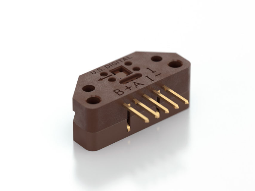
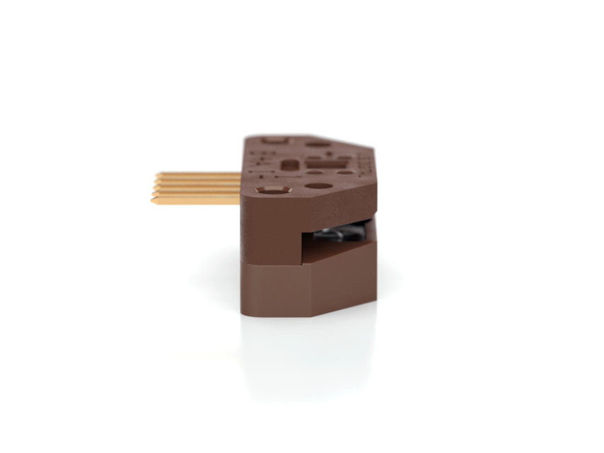
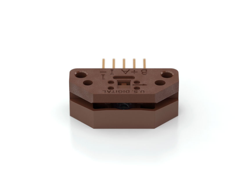
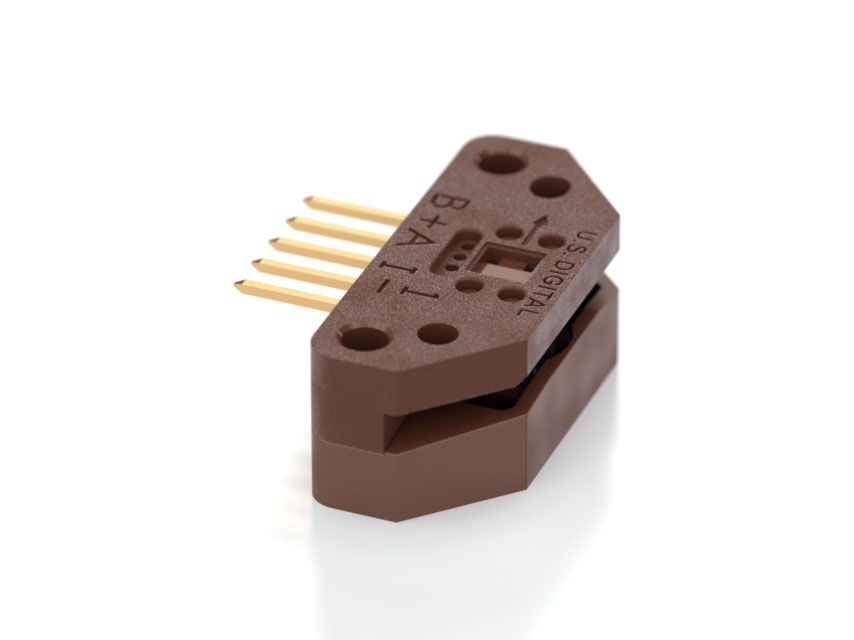
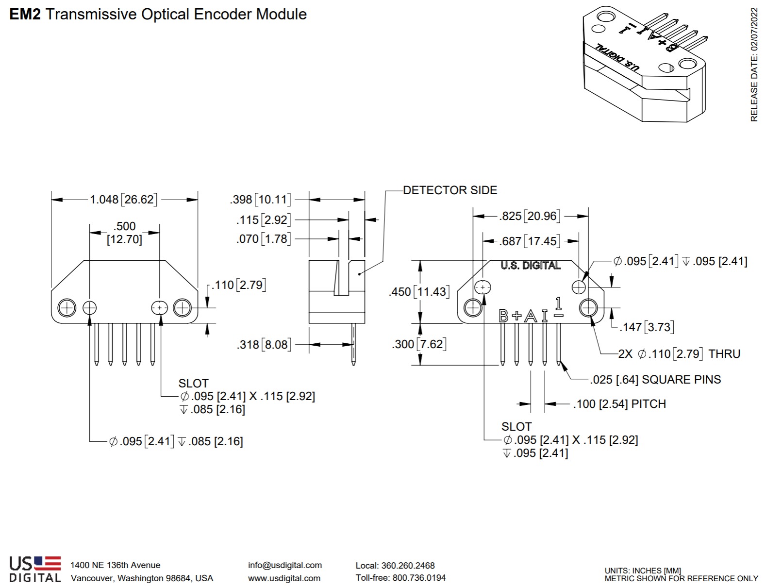
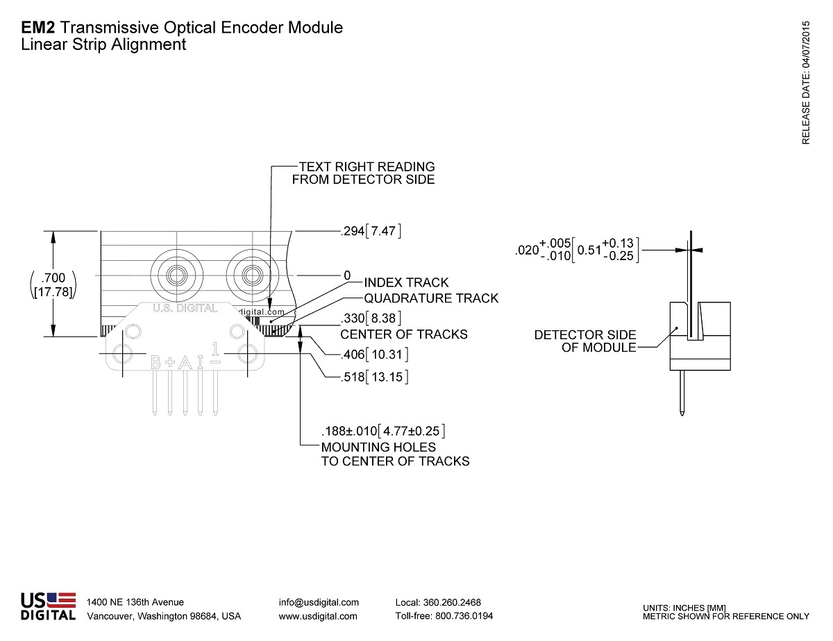
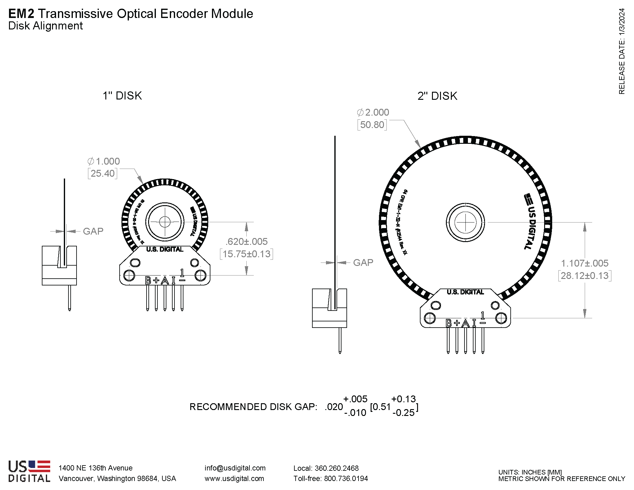
The EM2 is a transmissive optical encoder module designed to measure rotary or linear movement when paired with an encoder disk or linear strip. The EM2 consists of a lensed LED source and a monolithic detector IC enclosed in a small polymer package. The EM2 uses phased array detector technology, allowing for a wider gap tolerance and reliable performance even with some disk contamination.
The EM2 encoder module provides digital A & B quadrature outputs with an index channel. Each EM2 module is resolution-specific and is matched to the resolution of an encoder disk or linear strip. The EM2 module supports 12 different resolutions. The EM2 operates with a single 5V supply and provides single-ended outputs capable of sinking and sourcing 5mA. An internal 0.1 µF decoupling capacitor provides enhanced noise immunity.
For open collector and higher voltage applications, add the PC3 cable driver, or for differential cable driver outputs, add the PC4 cable driver.
Accessories such as encoder disks, linear strips, mating connectors, and cables are also available.
Download the EM2/EM1 comparison chart.
Product Specifications
COMPATIBLE 1" & 2" DISKS
1" DISKS
CPR
MODULE
1" DISK
2000
EM2-1-2000-I
DISK-1-2000-*-IE
2048
EM2-1-2048-I
DISK-1-2048-*-IE
2500
EM2-1-2500-I
DISK-1-2500-*-IE
4000
EM2-1-4000-I
DISK-1-4000-*-IE
4096
EM2-1-4096-I
DISK-1-4096-*-IE
5000
EM2-1-5000-I
DISK-1-5000-*-IE
*Represents the bore size
2" DISKS
CPR
MODULE
2" DISK
3600
EM2-2-3600-I
DISK-2-3600-*-IE
4000
EM2-2-4000-I
DISK-2-4000-*-IE
4096
EM2-2-4096-I
DISK-2-4096-*-IE
5000
EM2-2-5000-I
DISK-2-5000-*-IE
7200
EM2-2-7200-I
DISK-2-7200-*-IE
8000
EM2-2-8000-I
DISK-2-8000-*-IE
8192
EM2-2-8192-I
DISK-2-8192-*-IE
10000
EM2-2-10000-I
DISK-2-10000-*-IE
*Represents the bore size
COMPATIBLE 1" & 2" HUBDISKS
1" HUBDISKS
CPR
MODULE
1" HUBDISK
2000
EM2-1-2000-I
HUBDISK-1-2000-*-IE
2048
EM2-1-2048-I
HUBDISK-1-2048-*-IE
2500
EM2-1-2500-I
HUBDISK-1-2500-*-IE
4000
EM2-1-4000-I
HUBDISK-1-4000-*-IE
4096
EM2-1-4096-I
HUBDISK-1-4096-*-IE
5000
EM2-1-5000-I
HUBDISK-1-5000-*-IE
*Represents the bore size
2" HUBDISKS
CPR
MODULE
2" HUBDISK
3600
EM2-2-3600-I
HUBDISK-2-3600-*-IE
4000
EM2-2-4000-I
HUBDISK-2-4000-*-IE
4096
EM2-2-4096-I
HUBDISK-2-4096-*-IE
5000
EM2-2-5000-I
HUBDISK-2-5000-*-IE
7200
EM2-2-7200-I
HUBDISK-2-7200-*-IE
8000
EM2-2-8000-I
HUBDISK-2-8000-*-IE
8192
EM2-2-8192-I
HUBDISK-2-8192-*-IE
10000
EM2-2-10000-I
HUBDISK-2-10000-*-IE
*Represents the bore size
COMPATIBLE LINEAR STRIPS
LPI
MODULE
Linear Strip
MODULE
Linear Strip
1000
EM2-0-1000-N
LIN-1000-*-N
EM2-0-1000-I
LIN-1000-*-#
2000
EM2-0-2000-N
LIN-2000-*-N
EM2-0-2000-I
LIN-2000-*-#
* Represents length of Linear Strip
* Represents length of Linear Strip
ENVIRONMENTAL
Parameter
Value
Units
Operating Temperature
-25 to 100
C
Electrostatic Discharge, IEC 61000-4-2
± 4
kV
Vibration (10Hz to 2kHz, sinusoidal)
20
G
Shock (6 milliseconds, half-sine)
75
G
OPERATING CONDITIONS
PARAMETER
MIN.
MAX.
UNITS
NOTES
A/B Output Frequency
0
360
kHz
2000, 2048, 2500 CPR (1")
Disk RPM
0
(21.6 x 10^6) / CPR
RPM
2000, 2048, 2500 CPR (1")
Linear Strip Speed
0
360
in./sec.
1000, 2000 CPI (Linear)
Disk/Linear Strip Radial Position Tolerance
± .005
inch
ELECTRICAL SPECIFICATIONS
Specifications apply over the entire operating temperature/voltage range.
Typical values are specified at Vcc = 5.0V and 25C.
PARAMETER
MIN.
TYP.
MAX.
UNITS
CONDITIONS
Supply Voltage
4.5
5.0
5.5
V
Ripple < 100 mVpp
Supply Current
72
85
mA
no load
Low-level Output
0.5
V
IOL = 5 mA
High-level Output
2.0
V
IOH = -5 mA
Output Current Per Channel
-5
5
mA
Load Capacitance
100
pF
Output Rise Time
50
nS
± 5 mA load
Output Fall Time
50
nS
± 5 mA load
TIMING CHARACTERISTICS
ENCODING CHARACTERISTICS:
Specifications apply over the entire operating temperature/voltage range.
Values are for the worst error over full rotation.
Refer to the timing diagram below.
PARAMETER
SYMBOL
MIN.
TYP.
MAX.
UNITS
Symmetry
X, Y
108
190
252
°e
Quadrature
Z
45
90
135
°e
Index Pulse Width
Po
40
90
135
°e
Ch. I Rise After Ch. B or Ch. A Fall
t1
-40
ns
Ch. I Fall After Ch. B or Ch. A Rise
t2
25
ns
TIMING DIAGRAM:
CPI : The number of Cycles (C) of the A or B output Per Inch of linear strip movement.
CPR: The number of Cycles (C) of the A or B outputs Per Revolution.
Index (I): The index output goes high once per revolution, coincident with the low states of channels A and B, nominally 1/4 of one cycle (90 ° e).
One Shaft Rotation: 360 mechanical degrees.One Electrical Degree (°e): 1/360th of one cycle.One Cycle: 360 electrical degrees (° e). Each cycle can be decoded into 1 or 4 states, referred to as X1 or X4 resolution multiplication.
PPR : The number of resolvable Positions Per Revolution of the encoder disk with x4 quadrature decoding.
Quadrature (Z): The phase lag or lead between channels A and B in electrical degrees, nominally 90 ° e.
Symmetry: A measure of the relationship between (X) and (Y) in electrical degrees, nominally 180 ° e.
PIN-OUTS
Pin
Description
1
Ground
2
Index
3
A channel
4
+5VDC power
5
B channel
PRODUCT CHANGE NOTIFICATIONS
Title
Date
Description
Download
EM1 & EM2 Update - PCN 4199
1/14/2014
Based on our continuous process improvement program, US Digital is changing the current marking method for our EM1 and EM2 encoder modules to a serialization method. This change will allow for each module to have a unique code; the current marking method is based on a date code system that includes all encoder modules produced within a specific week / year. The serialization system will be based on a hexadecimal system.
Download
Additional Information
Product Notes
US Digital® warrants its products against defects in materials and workmanship for two years. See complete warranty for details.
Related
Press Releases
3D Model Downloads
Please
configure your product first
to download a 3D model. (Note: The formats below will become links if there are 3D models available.)
SolidWorks Format
IGES Format
Parasolid Format
STEP Format
Datasheet
Feedback
US Digital's mission is a commitment to quality and constant improvement. If you find an error to a product on this page, please let us know !
Save Your Configuration
Easily keep track of your custom part numbers
What is this feature?
While configuring your encoder, you can save your custom part number at any stage. This helps you keep track of multiple configurations without needing to start over or write anything down.
How does it work?
Click “Add This Configuration to Your List” after selecting your options.
Your saved part number will appear in a mini list below the configurator.
The list is stored locally in your browser and persists across product pages.
Enter a quantity to view default pricing.
What can you do with saved configurations?
When you're ready, visit the Saved Configurations List page to:
Review all saved part numbers
Fill out a form to send your selections to US Digital Customer Service
Receive follow-up to complete your order or get support
Why use it?
Save time by avoiding repeated configurations
Compare multiple part numbers side-by-side
Simplify communication with our support team
Got it!