PC4 Product Description
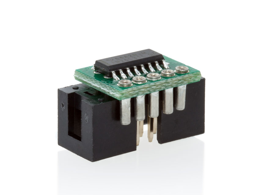
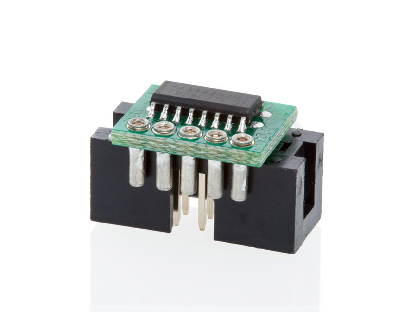
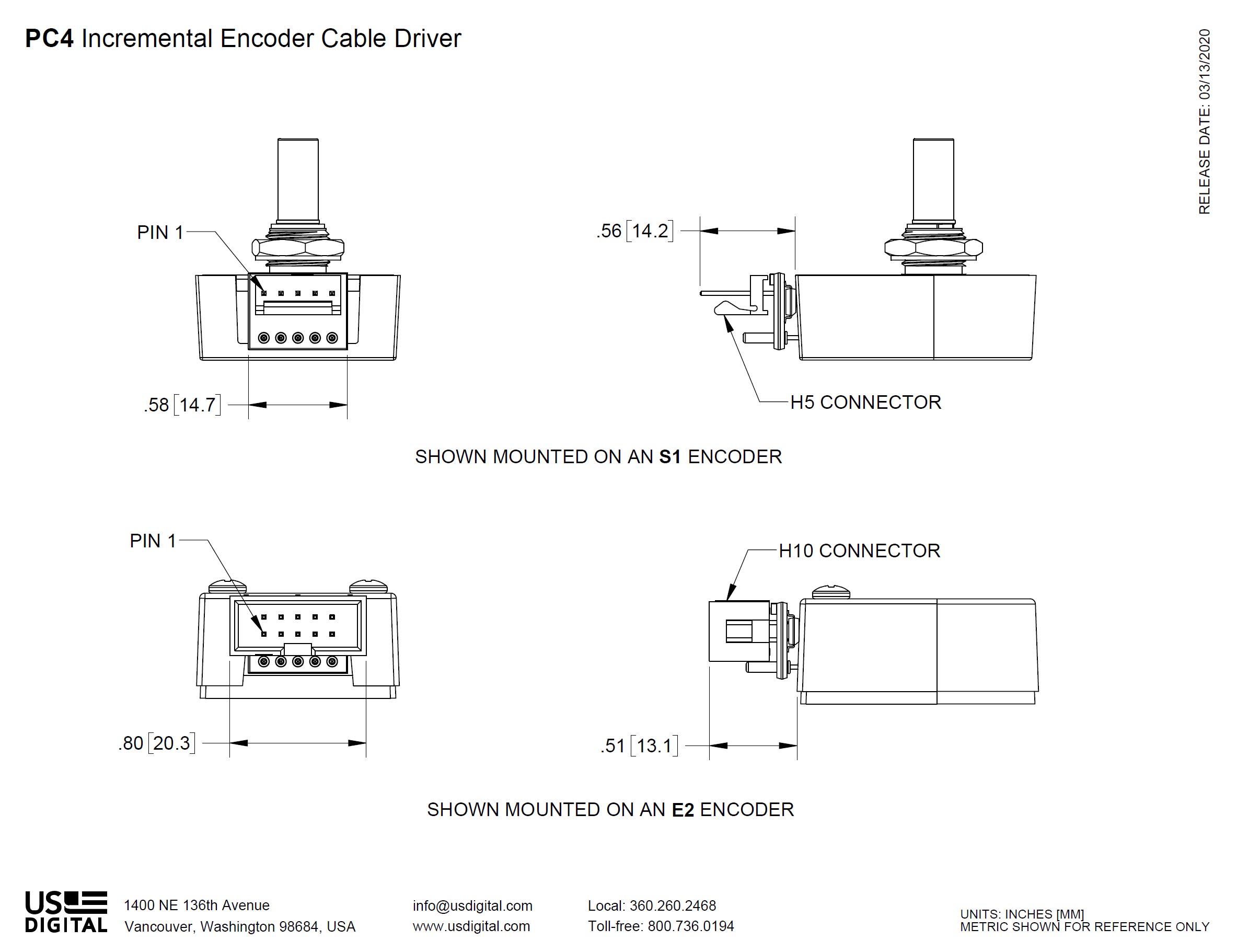
The PC4 is a small, plug-in RS-422 cable driver board that drives long cables up to one thousand feet using differential signaling to improve noise immunity. The PC4 can be used with the E2 , E3 , H1 , H3 , S1 , and S2 encoders. Each board has a 5-pin socket designed to plug into the 5 pins of the encoder.
On the output side, the PC4 can use ribbon cables for lengths up to 100 feet; twisted pair cables are recommended for longer lengths. An optional 120 Ω terminating resistor may be placed across each pair on the receiver side of the cable, matching the cable's characteristic impedance. When calculating the power requirements of the encoder side of the cable, including the current consumed by the module, the driver IC and any terminating resistors. Be sure to supply sufficient voltage to compensate for the voltage drop due to the resistance of the power and ground wires. If an RS-422 receiver chip such as 26C32 is used on the receiver side of the cable, a 0.1uF ceramic monolithic bypass capacitor across +5V and ground located within 1 inch of the receiver chip is recommended.
Product Specifications
ENVIRONMENTAL
PARAMETER
MIN.
MAX.
UNITS
Operating Temperature
-40
100
C
Electrostatic Discharge, Human Body Model
-2
2
kV
ELECTRICAL
PARAMETER
MIN.
TYP.
MAX.
UNITS
NOTES
Supply Voltage
4.5
-
5.5
Volts
-
Supply Current (26C31)
-
1
2
mA
-
Output High Voltage
2.5
-
-
Volts
IOH = -20 mA
Output Low Voltage
-
-
0.8
Volts
IOL = 20 mA
Propagation Time
-
-
15
ns
-
CONNECTORS
PRODUCT
DRIVER HEADER
CONNECTOR MATES WITH
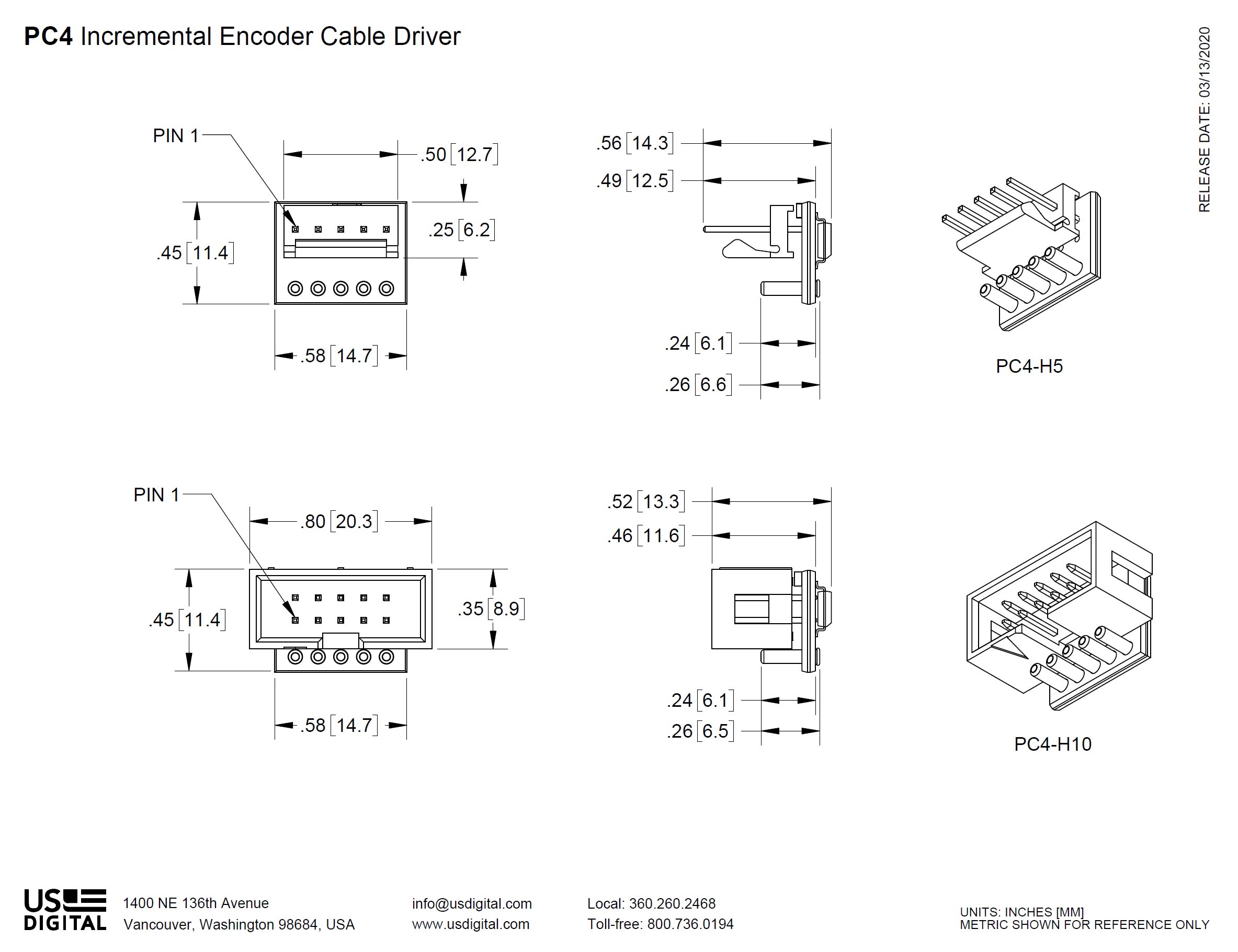
PC4-H10
TE# 103309-1
CON-C10*
PC4-H5
TE# 640456-5
CON-C5*
* US Digital part number. For more information see the Cables / Connectors page.
PIN-OUTS
PC4-H5 OUTPUT CONNECTOR
PIN
DESCRIPTION
1
Ground
2
Index
3
A channel
4
+5VDC power
5
B channel
PIN
DESCRIPTION
1
Ground
2
Ground
3
Index-
4
Index+
5
A- channel
6
A+ channel
7
+5VDC power
8
+5VDC power
9
B- channel
10
B+ channel
Product Change Notifications
Title
Date
Description
Download
PC3-H5, PC4, PC5, and PC6 Laser Markings - PCN 6228
9/27/2017
This notification is to inform our customers of a product marking a change for the PC3-H5, PC4, PC5, and PC6 products. The purpose of this change is to create a more robust solution by utilizing laser marking versus the current paper label solution. The products affected will now be laser marked.
Download
Additional Information
Product Notes
Cables and connectors are not included and must be ordered separately.
US Digital® warrants its products against defects in materials and workmanship for two years. See complete warranty for details.
Related
3D Model Downloads
Please
configure your product first
to download a 3D model. (Note: The formats below will become links if there are 3D models available.)
SolidWorks Format
IGES Format
Parasolid Format
STEP Format
Datasheet
Feedback
US Digital's mission is a commitment to quality and constant improvement. If you find an error to a product on this page, please let us know !
Save Your Configuration
Easily keep track of your custom part numbers
What is this feature?
While configuring your encoder, you can save your custom part number at any stage. This helps you keep track of multiple configurations without needing to start over or write anything down.
How does it work?
Click “Add This Configuration to Your List” after selecting your options.
Your saved part number will appear in a mini list below the configurator.
The list is stored locally in your browser and persists across product pages.
Enter a quantity to view default pricing.
What can you do with saved configurations?
When you're ready, visit the Saved Configurations List page to:
Review all saved part numbers
Fill out a form to send your selections to US Digital Customer Service
Receive follow-up to complete your order or get support
Why use it?
Save time by avoiding repeated configurations
Compare multiple part numbers side-by-side
Simplify communication with our support team
Got it!
 My Saved List