E3 Motor Encoder

E3 Features

  • Kit Version for mounting on a motor or other shaft
  • Support 22 shaft sizes (2 to 25 mm and 1/8 in. to 1 in.)
  • For NEMA 23 to NEMA 34 and larger motors
  • 20 Resolutions from 64 to 10,000 CPR (256-40,000 PPR)
  • 2 channel quadrature output with an optional index channel
  • Choice of 2 base styles and 2 cover options
  • High retention connector/cable (sold separately)

See more info below

Configure the E3

E3 Product Description

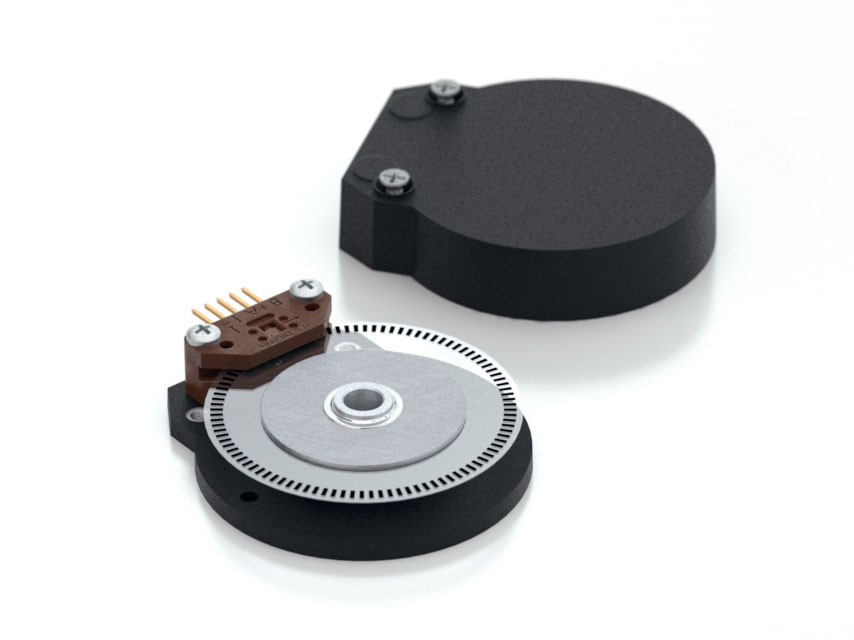
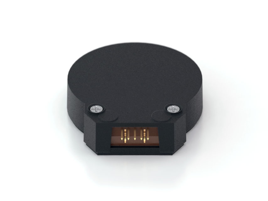
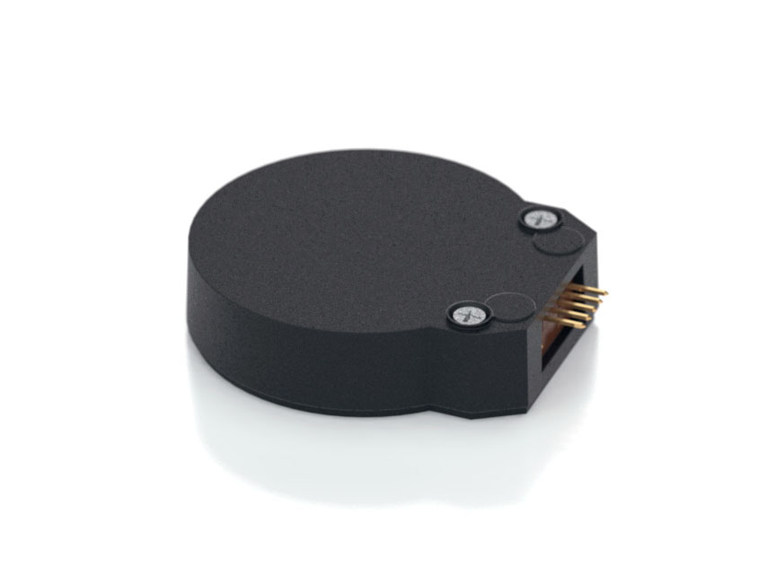
The US Digital E3 motor encoder mounts directly to a motor or other rotating shaft. This optical encoder features a rugged, glass-filled polymer housing and is designed for easy installation and removal.

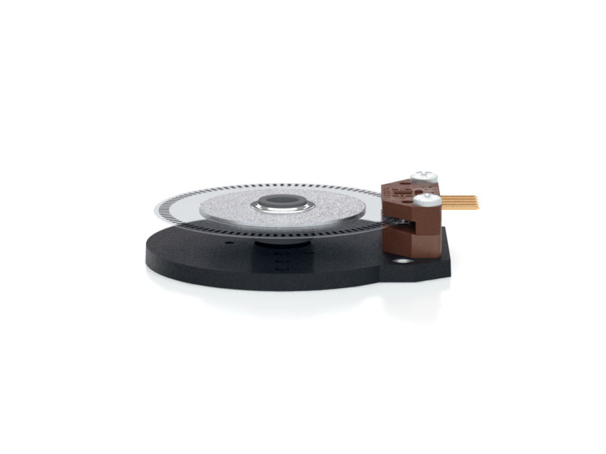
The E3 optical rotary encoder contains a precision machined aluminum hub with a specially patterned Mylar disk. This disk, in combination with our proprietary optical encoder module, creates a system that is highly tolerant to mechanical misalignment. 

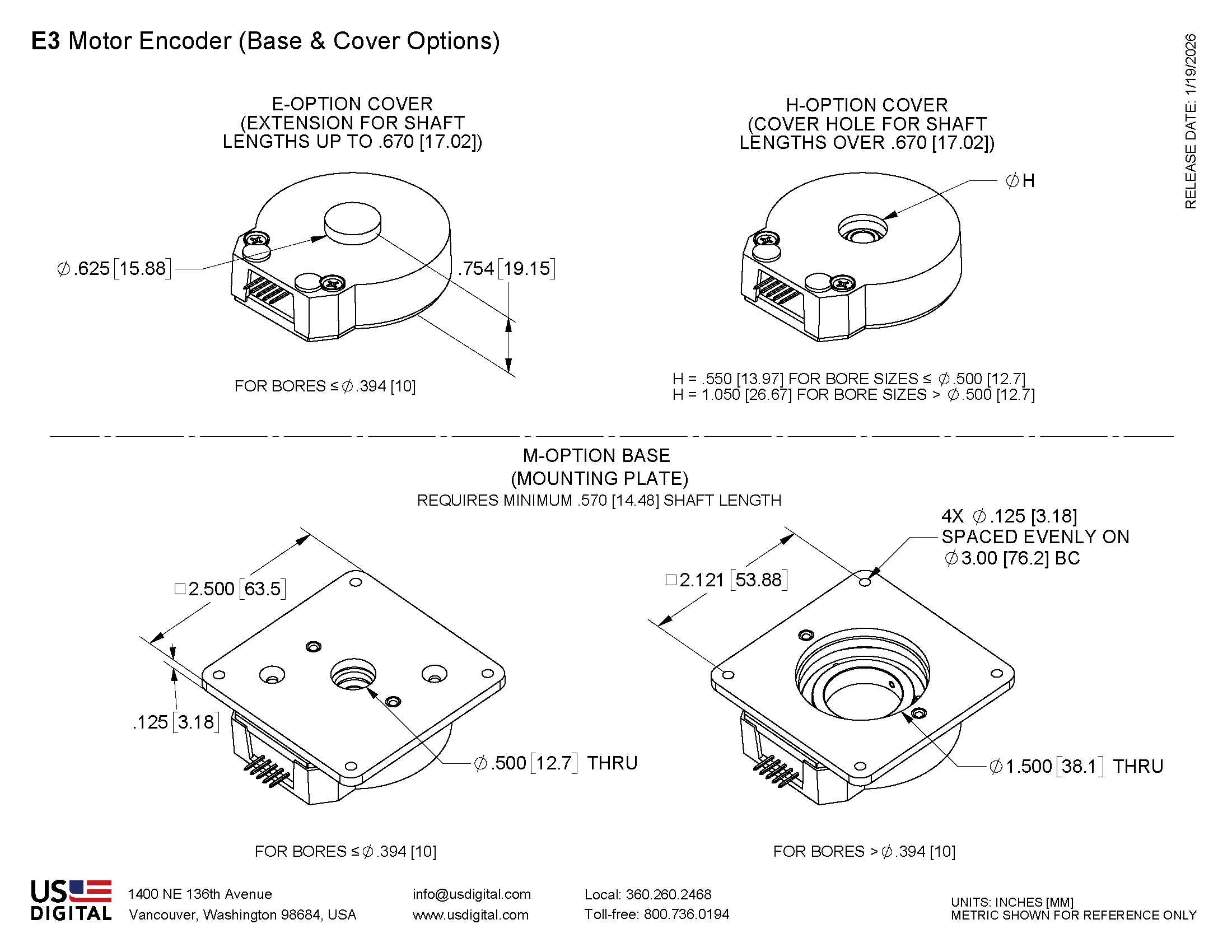
The E3 is available with two base configurations and three cover styles, which allow it to fit a wide range of applications. The output for this optical rotary encoder is single-ended. If your application requires a differential output (due to needing a cable over 10 feet or is located in an electrically noisy environment) you can either add a PC4 / PC5 differential line driver or check out our E6, which includes an optional differential output.

This incremental encoder is designed for use with a high-retention connector. After making each selection in the Product Configurator, compatible cables and connectors will be displayed below and must be purchased separately.

Product Specifications

ENVIRONMENTAL

PARAMETER

VALUE

UNITS

Operating Temperature, CPR < 2000

-40 to 100

C

Operating Temperature, CPR ≥ 2000

-25 to 100

C

Electrostatic Discharge, IEC 61000-4-2

± 4

kV

Vibration (10Hz to 2kHz, sinusoidal)

20

G

Shock (6 milliseconds, half-sine)

75

G

MECHANICAL

PARAMETER

VALUE

UNITS

Max. Shaft Axial Play

±0.010

in.

Max. Shaft Runout

0.004 T.I.R.

in.

Max. Acceleration

250000

rad/sec²

For CPR ≤ 2500:
Max. RPM (1)
Max. A/B Frequency
e.x. CPR=2500, Max. RPM=7200
e.x. CPR=100, Max. RPM=60000


minimum value of ((18 x 10^6) / CPR) and (60000)
300


RPM
kHz

For CPR = 3600, 4000, 4096, 5000:
Max. RPM (1)
Max. A/B Frequency


(21.6 x 10^6) / CPR
360


RPM
kHz

For CPR = 7200, 8000, 8192, 10000:
Max. RPM (1)
Max. A/B Frequency


(43.2 x 10^6) / CPR
720


RPM
kHz

Typical Product Weight

1.28

oz.

Codewheel Moment of Inertia

8.9 x 10^-5 for bore < 12mm
4.0 x 10^-4 for bore ≥ 12 mm

oz-in-s²

Hub Set Screw

#3-48 or #4-48


Hex Wrench Size

0.050

in.

Encoder Base Plate Thickness

0.135

in.

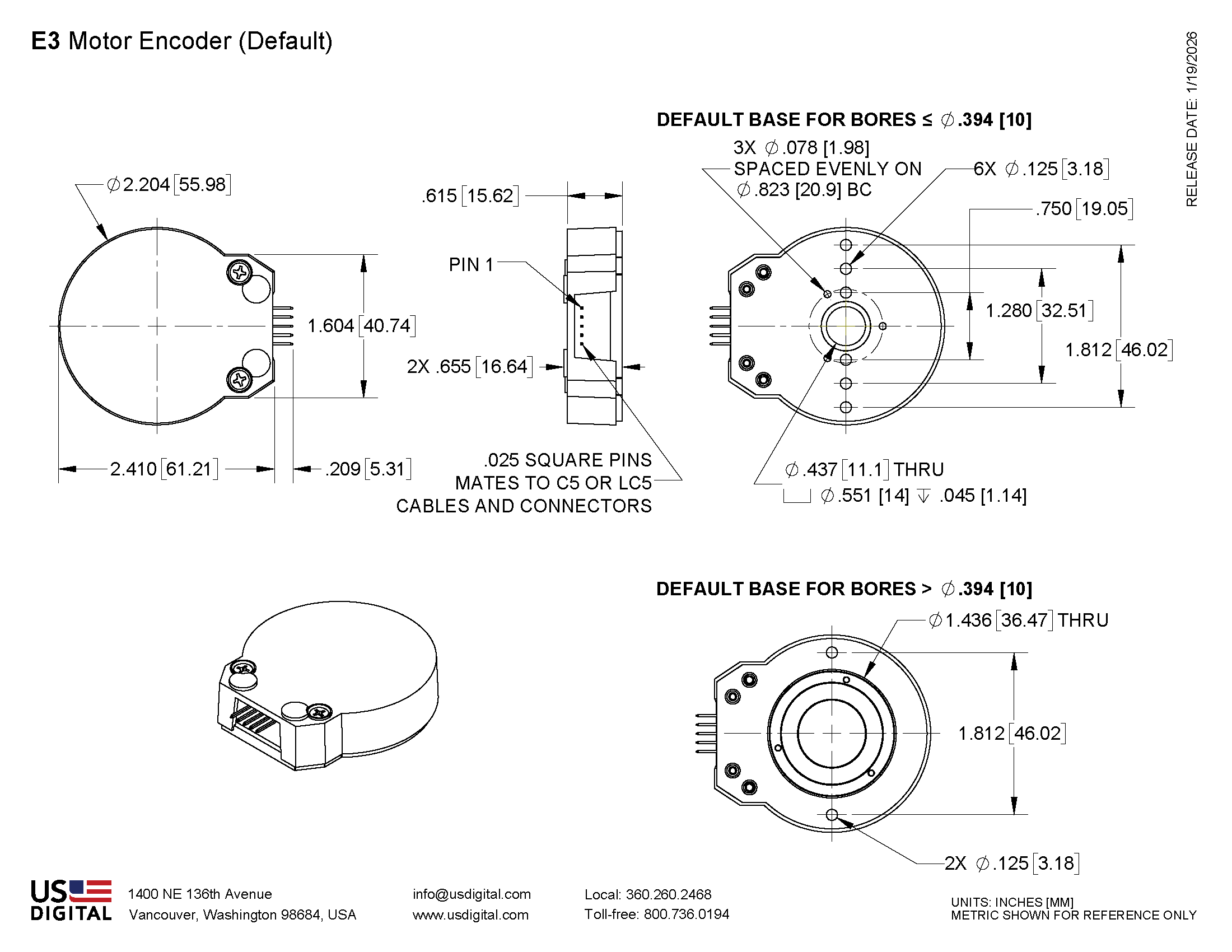
3 Mounting Screw Size

#0-80


3 Screw Bolt Circle Diameter (2)

0.823 ± 0.005

in.

2 Mounting Screw Size

#2-56 or #4-40


2 Screw Bolt Circle Diameter

0.750 ± 0.005

in.

2 Screw Bolt Circle Diameter

1.280 ± 0.005

in.

2 Screw Bolt Circle Diameter

1.812 ± 0.005

in.

Required Shaft Length (3)
  With E-option (2)
  With H-option

0.445 to 0.525
0.445 to 0.670
> 0.445

in.
in.
in.

Index alignment to hub set screw

180 ± Typical

degrees

Technical Bulletin TB1001 - Shaft and Bore Tolerances

Download

(1) 60000 RPM is the maximum rpm due to mechanical considerations. The maximum RPM due to the module's maximum frequency response is dependent upon the module’s resolution (CPR).

(2) Only for shaft diameters < 0.472".

(3) Add 0.125" to all required shaft lengths when using M-option.

TORQUE SPECIFICATIONS

PARAMETER

VALUE

TORQUE

Hub Set Screw

2-3

in-lbs

Cover Screw

2-4

in-lbs

Base Mounting Screw (#0-80)

1-2

in-lbs

Base Mounting Screw (#2-56)

2-3

in-lbs

Base Mounting Screw (#4-40)

4-6

in-lbs

Adapter Plate Mounting Surface (#2-56 screws)

2-3

in-lbs

Adapter Plate Mounting Surface (#4-40 screws)

4-6

in-lbs

Module Mounting Screw

3.5-4

in-lbs

PHASE RELATIONSHIP

A leads B for clockwise shaft rotation, and B leads A for counterclockwise rotation viewed from the cover side of the encoder.

ELECTRICAL

  • Specifications apply over the entire operating temperature range.

  • Typical values are specified at Vcc = 5.0Vdc and 25°C.

  • For complete details, see the EM1 and EM2 product pages.

PARAMETER

MIN.

TYP.

MAX.

UNITS

CONDITIONS

Supply Voltage

4.5

 5.0

5.5

V


Supply Current


27
54
72

33
62
85

mA
mA
mA

CPR < 1000, no load 
CPR ≥ 1000 and < 3600, no load
CPR ≥ 3600, no load

Low-level Output


0.05
0.25

0.5
0.5

V
mA
mA
mA

IOL = 8mA max., CPR < 3600
IOL = 5mA max., CPR ≥ 3600
no load, CPR < 3600
no load, CPR ≥ 3600

High-level Output

2.0
2.0


4.8
3.5


V
V
V
V

IOH = -8mA max., CPR < 3600
IOH = -5mA max., CPR ≥ 3600
no load, CPR < 3600
no load, CPR ≥ 3600

Output Current Per Channel

-8
-5


8
5

mA
mA

CPR < 3600
CPR ≥ 3600

Output Rise Time


110
50


nS
nS

CPR < 3600
CPR ≥ 3600

Output Fall Time


35
50


nS
nS

CPR < 3600
CPR ≥ 3600

PIN-OUT

PIN

DESCRIPTION

1

Ground

2

Index

3

A channel

4

+5VDC power

5

B channel

Note: 5-pin single-ended mating connector is CON-C5 or CON-LC5

ACCESSORIES

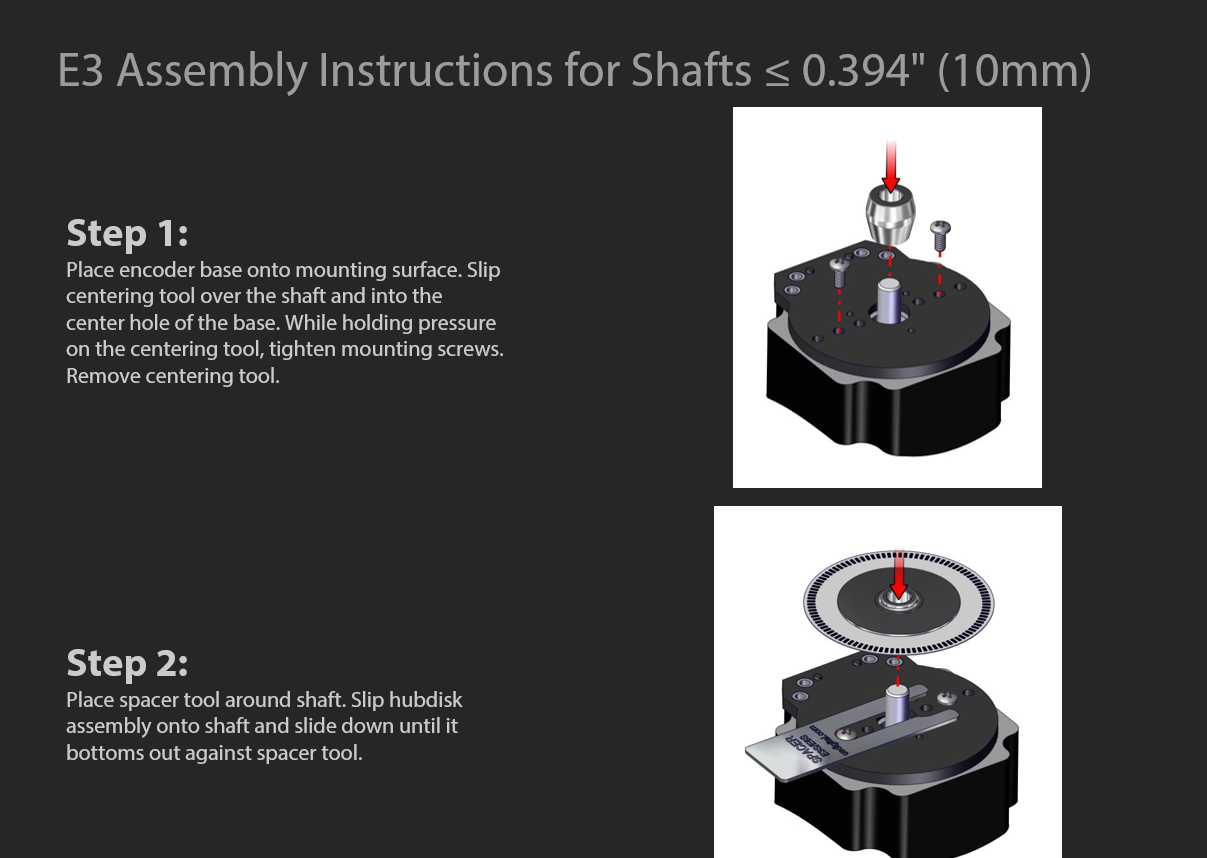
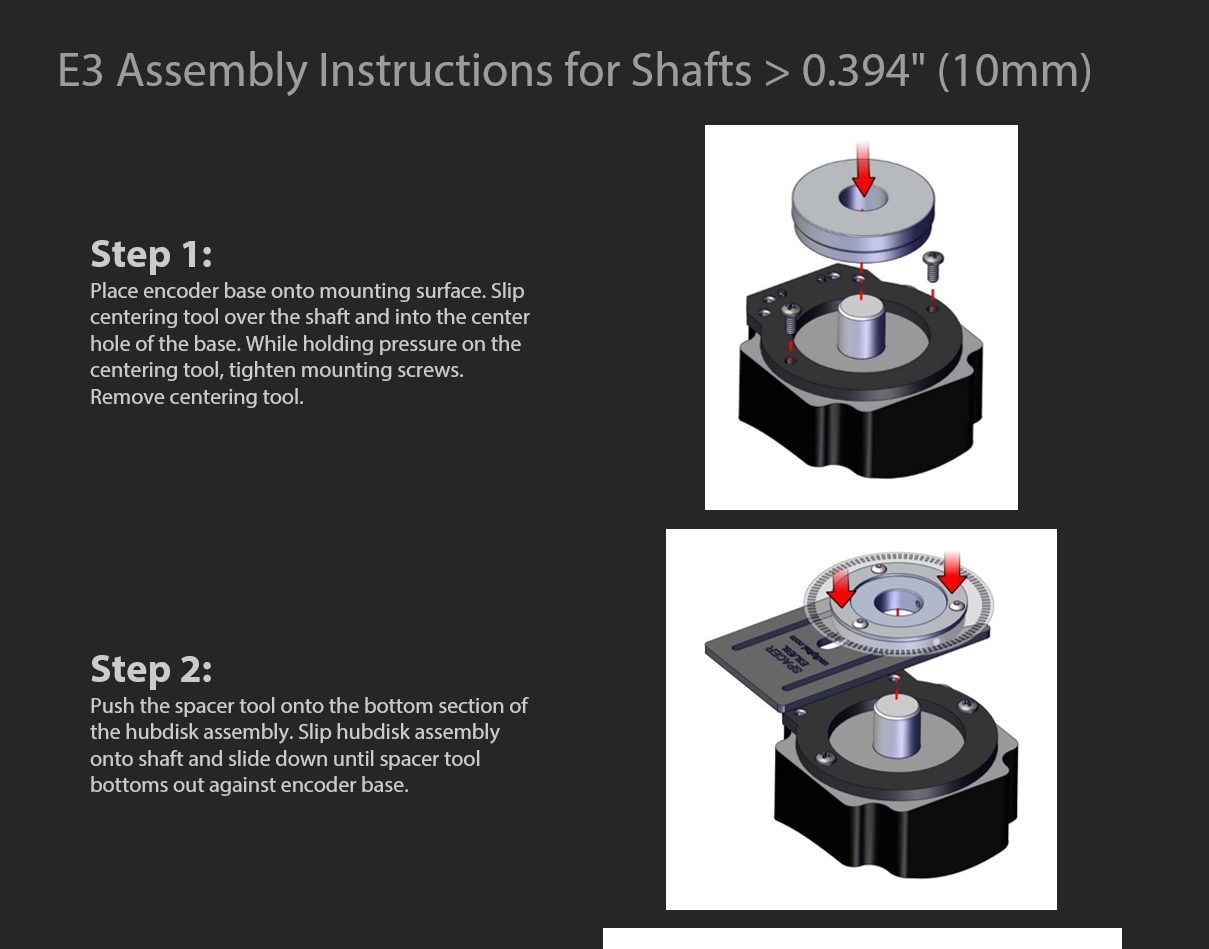
1. Centering Tool

Part #: CTOOL - (Shaft Diameter)
This reusable tool centers the shaft within the encoder base during assembly. It is required for the proper functioning of the encoder.

2. Hex Tool

Part #: HEXD-050
Hex driver, 0.050" flat-to-flat for #3-48 or #4-48 set screws. Included with -B or -packaging options for order quantities of 10 or more.

Part #: HEXW-050
Hex wrench, 0.050" flat-to-flat for #3-48 or #4-48 set screws. Included with -B or -packaging options for order quantities of 9 or less. Included with -packaging option for all order quantities.

3. Spacer Tool

This reusable tool sets the proper spacing between the disk and sensor during assembly. It is required for the proper functioning of the encoder.

Part #: SPACER-E3S
Description:
 For shafts ≤ 0.394"

Part #: SPACER-E3L
Description:
 For shafts 12mm - 1"

4. Screws

Part #: SCREW-080-250-PH
Description: Pan Head, Philips #0-80 UNF x 1/4"
Use: Base Mounting
Quantity Required: 3
Screws are not included

Part #: SCREW-256-250-PH
Description: Pan Head, Philips #2-56 UNC x 1/4"
Use: Base Mounting
Quantity Required: 2
Screws are not included

Part #: SCREW-348-125-SS
Description: Socket Head Set Screw, 3-48 UNC x 1/8"
Use: Hub/Disk Mounting for 12mm - 1" Bore
Quantity Required: 2
Screws are included

Part #: SCREW-440-250-PH
Description: Pan Head, Philips #4-40 UNC x 1/4"
Use: Base Mounting
Quantity Required: 2
Screws are not included

Part #: SCREW-440-500-PH
Description: Pan Head, Phillips #4-40 UNC x 1/2"
Use: Module Mounting
Quantity Required: 2
Screws are included

Part #: SCREW-440-625-FH
Description: Flat Head, Phillips 4-40 UNC x 5/8"
Use: Cover Mounting
Quantity Required: 2
Screws are included

Part #: SCREW-448-063-SS
Description: Socket Head Set Screw, 4-48 UNC x 1/16"
Use: Hub/Disk Mounting for 5/16" - 10mm Bore
Quantity Required: 1
Screw is included

Part #: SCREW-448-125-SS
Description: Socket Head Set Screw, 4-48 UNC x 1/8"
Use: Hub/Disk Mounting for 2mm - 1/4" Bore
Quantity Required: 1
Screw is included

PRODUCT CHANGE NOTIFICATIONS

Title

Date

Description

Download

E3 and E6 Packaging Option Changes - PCN 7357

2/21/2024

As part of our ongoing continuous improvement efforts, US Digital is implementing a change to the packaging options for our E3 and E6 encoders. We will now include a centering tool with all packaging options. We are implementing this change to ensure that the encoder is properly assembled using the tools as designed, as per our assembly instructions. A centering tool is needed to properly center the encoder base to the mounting surface. By including the centering tool, customers will no longer need to purchase them separately.

Download

E3 Base Mold Update - PCN 6804

1/24/2019

As part of our ongoing continuous improvement efforts, and in order to enhance both function and appearance, multiple improvements are being incorporated into a plastic component redesign.The plastic base mounting holes and center hole counter-bore are increasing in size, and the four press-fit threaded inserts are being replaced with thread inserts that are over-molded into the base.With exception of the features outlined below, the new parts are dimensionally equivalent and will fit within the same envelope of the previous parts.

Download

2" Hub/Disk Assembly Screw Change - PCN 6644

9/27/2018

As part of our ongoing continuous improvement efforts, the screws used in the assembly of the 2" hub/disk assembly, that is with a bore of 12mm and larger, will be changed from a black oxide to a zinc plated screw.The zinc plating improves corrosion resistance as well as alleviates any potential for oil residue.The plating change has no effect on form, fit or function of our hubdisk assembly.

Download

Update to 1" and 2" Disks - PCN 6232

5/24/2018

This notice is to inform our customers of a minor disk design modification that is being implemented for standard 1" and 2" disks. This is a continuation of a change that was implemented for our index disks in 2015.We are revising the text on the disk, adding the US Digital logo and a line that is used internally by our manufacturing group.The change does not affect the quadrature or index tracks; therefore, it has no impact on form, fit or function.

Download

Hub Set Screw Production Change - PCN 5367

7/20/2015

As part of our ongoing continuous improvement efforts, US Digital is implementing a change related to the production of our 5/16" (.313), 8mm (.315), 3/8" (.375), and 10mm (.394) HUBDISK assemblies. We are adding a low strength threadlocker to the set screw during our assembly process to assist in securing the set screw in the hub during transportation. This will aid in the set screw retention of these specific hub sizes; ensuring the retention is sufficient and avoid the potential of them backing out of the hub assembly during transit. This change does not affect form, fit or function.

Download

Laser Marking - PCN 5253

6/17/2015

As part of our ongoing continuous improvement efforts, US Digital is changing the labeling/marking method for our E3, E6, H3, H6, S1, S2 and S6 products.

Download

EM1 & EM2 Update - PCN 4199

1/14/2014

Based on our continuous process improvement program, US Digital is changing the current marking method for our EM1 and EM2 encoder modules to a serialization method. This change will allow for each module to have a unique code; the current marking method is based on a date code system that includes all encoder modules produced within a specific week / year. The serialization system will be based on a hexadecimal system.

Download

EM1 LED Die - PCN 1016

2/7/2013

As part of US Digital's continual assurance of supply strategy, we have qualified additional sources for our LED die used in our EM1 encoder module, which in turn impacts all of the following products:EM1, E2, E3, E5, E6, H1, H15, H3, H5, H6, HB5M, HB6M, HD25, PE, S1, S2, S5, S6, T5 and T6The device specification will remain the same, i.e. there will be no change to form, fit or function of the product(s) as specified by US Digital. The appropriate quality and reliability testing has been performed on representative products to ensure normal parametric distribution, consistent with US Digital's quality and reliability standards.

Download

Additional Information

Product Notes

  • Cables and connectors are not included and must be ordered separately.
  • US Digital® warrants its products against defects in materials and workmanship for two years. See complete warranty for details.

Assembly Instructions & Videos

Related


3D Model Downloads

Please configure your product first to download a 3D model.
(Note: The formats below will become links if there are 3D models available.)

    • SolidWorks Format
    • IGES Format
    • Parasolid Format
    • STEP Format

    Datasheet


    Product Configurator

    TO VIEW PRICING CHOOSE EITHER OPTION 1 OR 2 BELOW.

    Questions? Contact our support team.

    Option 1: Enter the Product Part Number

    Already have your part number (e.g., E5-5000-394-IE-S-D-D-3)? Enter it in the following field.

    Option 2: Build your Product

    Customize your product step-by-step. Need help? Our support team is here to help.

    We recommend enabling Javascript when using the product configurator.


    Saved Configurations ( ):

    Configurations currently in your list (0)


    Feedback

    US Digital's mission is a commitment to quality and constant improvement. If you find an error to a product on this page, please let us know!

    Save Your Configuration

    Easily keep track of your custom part numbers

    What is this feature?

    While configuring your encoder, you can save your custom part number at any stage. This helps you keep track of multiple configurations without needing to start over or write anything down.

    How does it work?
    • Click “Add This Configuration to Your List” after selecting your options.
    • Your saved part number will appear in a mini list below the configurator.
    • The list is stored locally in your browser and persists across product pages.
    • Enter a quantity to view default pricing.
    What can you do with saved configurations?

    When you're ready, visit the Saved Configurations List page to:

    • Review all saved part numbers
    • Fill out a form to send your selections to US Digital Customer Service
    • Receive follow-up to complete your order or get support
    Why use it?
    • Save time by avoiding repeated configurations
    • Compare multiple part numbers side-by-side
    • Simplify communication with our support team
    Saved Configurations Example Saved configuration part numbers screenshot

    Compare Items (Max 3):