T7 Product Description The T7 is now IP68 rated. For more details, download the T7_IP_Certification .
The T7 is a solid-state absolute inclinometer that senses tilt angles over a full 360° range in a single axis. The T7 incorporates several breakthroughs to create a new type of inclinometer that is rugged, compact, fast, flexible, and easy to use.
The T7 is available in several interface and protocol options. The physical interface can be RS232 or RS485. The protocol can be either US Digital's serial protocol or Modbus RTU. The RS232 version supports a single T7 with up to 100 ft of cable. For users that need longer cable lengths or multiple T7s on a single bus, the RS485 version supports up to 32 T7s on the bus. Power for each T7 is supplied over the network cable.
The Modbus RTU version is suitable for users that require an industry-standard, open protocol. The host may access each T7 on the bus using standard Modbus read/write register function codes.
The T7 calculates the tilt angle (inclination) by sensing the acceleration from solid-state accelerometers integrated into a monolithic chip. Gravity, centrifugal forces, and linear speed changes are all forms of acceleration. The T7 will report the mathematically calculated tilt angle based on all sensed acceleration(s).
The serial port interface provides an efficient way to read and write data to a network of T7s. All configurations and parameters are stored in nonvolatile memory. A Windows demo application is provided to display the angles and temperature and set operating modes, orientation, zero position, damping / averaging time, direction, and more for every T7 on the network. In addition, a Windows DLL gives the user a set of simple functions to read and write data to a network of T7s.
Typical applications include heavy construction equipment, dredging machinery, mining equipment, solar tracking, and warehouse automation.
WARNING: This product can cause exposure to substances, such as phthalate plasticizers , known to the State of California to cause cancer and reproductive harm. For more information, go to oehha.ca.gov/proposition-65 .
Product Specifications
ENVIRONMENTAL
PARAMETER
MIN.
TYP.
MAX.
UNITS
Operating Temperature
-10
25
70
C
Acceleration Limit (for internal sensor)
± 50000
G
Ingress Protection Rating
IP68
Electrostatic Discharge, IEC-61000-4-2
± 15
kV
ELECTRICAL
PARAMETER
MIN.
TYP.
MAX.
UNITS
Supply Voltage
5.5
24
30
V
Supply Current (Operating, 22C ambient)
Bandwidth
8
Hz
MECHANICAL
PARAMETER
SPECIFICATION
Case Material
Glass filled polycarbonate
Weight
1.2 oz (34 g) nom.
RS232 VERSIONS
PARAMETER
MAX.
UNITS
Number of T7s on bus
1
Maximum total cable length
100
feet
Note: The T7 can drive 100 ft. of cable. Some PCs have limited drive on the RS232 bus which will limit the maximum cable length to less than 100 ft.
RS485 VERSIONS
PARAMETER
MAX.
UNITS
Number of T7s on bus
32
Maximum total cable length
1000
feet
1) Uses RS485 two-wire network
2) Uses "fail-safe" drivers so bias resistors are not required
3) In most applications, the RS485 network does not need termination at 9600 bps with less than 1000 feet of cable. If termination is used, the RS485 network should be terminated with a 120-150 ohm resistor between BUS+ and BUS- at the source and at the last T7-1-485 /T7-1-MOD4 on the network. US Digital terminating CAN cables (CA-CM-PS-CFTR ) may be used at the last T7 on the bus to terminate it.
RS485 POWER SUPPLY VOLTAGE
For a given network size, a minimum T7-1-485/T7-1-MOD4 power supply voltage is needed to ensure that the last T7 on the network is powered by at least 5.5V. The minimum power supply voltage can be calculated based on the number of networked T7s, the cable resistance/configuration, and the current consumption of each T7 as a function of voltage. The following tables show the recommended minimum power supply voltage as a function of cable length and number of T7s for several common network wiring schemes. The tables assume that US Digital T7 cables with a resistance of 3.3 ohms per hundred feet (#22 AWG) for the two power lines are used. USD T7 cables have a twisted pair for the data wires and can be used for both RS485 and RS232 versions. The following data is for room temperature (22C) operation.
Recommended minimum power supply voltage for T7s equally spaced on a total cable length, L. Stub length from T-adapter to a T7 is 6 feet. N is the number of T7's in the network.
Recommended minimum power supply voltage for T7s spaced 9 feet apart after an initial leader cable length, L. Stub length from T-adapter to a T7 is 6 feet.
MODBUS VERSION
The RS232 and RS485 versions of the T7 are available with the Modbus RTU protocol. Modbus Function Codes 3 (Read Holding Register) and 6 (Write Single Register) are supported. User defined Function Code 110 is used for some operations such as setting serial port parameters and the device address. If non-US Digital Modbus devices are connected to the same bus, it is recommended that only Function Codes 3 and 6 be used for non-USD devices.
ACCURACY AND NOISE
PARAMETER
MAX.
UNITS
TEST CONDITIONS
Axis 2 Relative Angular Error
±0.1
Angular Degrees
0°C to 70°C, on-axis
Up to ±5° off-axis operation is possible with 2σ (95%) confidence on the maximum angular error
DAMPING TIME, MILLISECONDS
STANDARD DEVIATION (σ )OF ANGLE NOISE, DEGREES
95% CONFIDENCE INTERVAL(± 2σ ), DEGREES
10
.060
.121
20
.037
.074
50
.021
.042
100
.015
.029
200
.010
.021
500
.007
.014
1000
.005
.011
2000
.004
.008
5000
.003
.006
Measurements taken at 25°C
Damping time is a user programmable parameter
AXIS ORIENTATION
Axis Orientation:
Note: T7 shown with factory default configuration.
NOISE FILTERING
The T7 uses a FIR (Finite Impulse Response) digital filter to provide electronic damping of the angle readings. The digital filter's impulse response has a triangular weighting that decays linearly to zero. The damping time is user programmable from 2 milliseconds to 5000 milliseconds. Since the sensor bandwidth is 8 Hz, damping times below 125 milliseconds do not provide any faster response. Increasing the damping time will average more samples together to form the reported angle. This will reduce noise in the output but increase the response time.
INTERFACING WITH A HOST COMPUTER
An inclinometer network assembled with the RS232 or RS485 version of the T7 is shown below.
US Digital sells all the cables and connectors needed to wire a T7 network. The T7 uses the same connector for all interface versions.
Regardless of the interface option, a host PC, PLC, or microcontroller communicates with a network of T7s by sending/receiving simple serial port commands over the RS232 or RS485 bus.
NETWORK ADDRESS
T7-1-232, T7-1-485 Addressing
Each T7 on the network must be assigned a unique address from 1 to 100 or 127 (decimal). Address assignment is optional for the RS232 version. All T7s are shipped with a default address of 127. Address 126 is a special broadcast address - all T7s will listen and respond to commands sent to this address. To assign an address to a T7 unit, connect one T7 to a PC using a USB to RS232/RS485 adapter. The address can be set using the included PC-based "T7 Demo" software. Alternately, a host computer can send the "Set Address" serial port command to the T7. This procedure only needs to be done once for each T7 since the address is stored in non-volatile flash memory.
T7-1-MOD2, T7-1-MOD4 Addressing
Each T7 on the network must be assigned a unique address from 1 to 100 (decimal). All T7s are shipped with a default address of 127. Address 0 is the Modbus broadcast address. To assign an address to a T7 unit, connect one T7 to a PC using a USB to RS232/RS485 adapter. The address can be set using the included PC-based "T7 Demo" software. Alternately, a host computer can send a special "Set Address" command to the T7. This procedure only needs to be done once for each T7 since the address is stored in non-volatile flash memory.
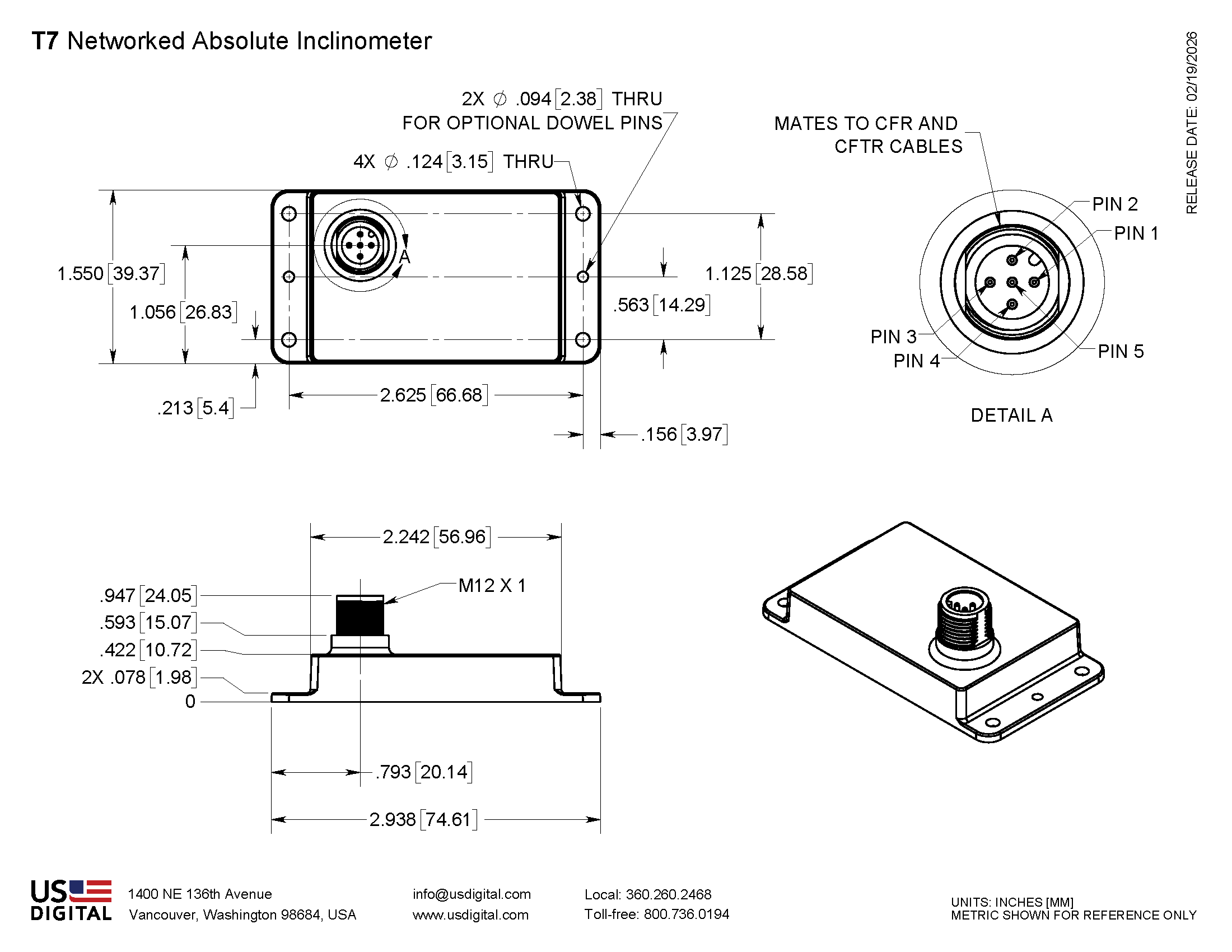
J1 PIN-OUT
Pin
Description
1
Shield
2
Vin
3
GND
4
TXD / BUS+
5
RXD / BUS-
DEFAULT CONFIGURATION
All T7 units ship from US Digital with a default configuration. Configuration parameters are stored in non-volatile flash memory and can be easily changed by the user. The specifications are shown below. However, in larger quantities, units can be preconfigured with any of the available settings noted in the T7 Communication User Guide or T7 Modbus Communication User Guide . Please contact customer service.
Default Configuration:
Address = 127
Single-axis version uses Axis 2
Angle output range set to +/-180 (-179.99 to 179.99) deg.
Counting Direction set to "forward"
Angle Offset set to 0
Damping time = 1000 milliseconds
USD protocol versions use 115200 bps, 8 data bits, no parity, 1 stop bit
Modbus protocol versions use 9600 bps, 8 data bits, even parity, 1 stop bit
Additional Information
Product Notes
Cables and connectors are not included and must be ordered separately.
US Digital® warrants its products against defects in materials and workmanship for two years. See complete warranty for details.
Guides and Additional Documentation
Software
3D Model Downloads
Please
configure your product first
to download a 3D model. (Note: The formats below will become links if there are 3D models available.)
SolidWorks Format
IGES Format
Parasolid Format
STEP Format
Datasheet
Feedback
US Digital's mission is a commitment to quality and constant improvement. If you find an error to a product on this page, please let us know !
Save Your Configuration
Easily keep track of your custom part numbers
What is this feature?
While configuring your encoder, you can save your custom part number at any stage. This helps you keep track of multiple configurations without needing to start over or write anything down.
How does it work?
Click “Add This Configuration to Your List” after selecting your options.
Your saved part number will appear in a mini list below the configurator.
The list is stored locally in your browser and persists across product pages.
Enter a quantity to view default pricing.
What can you do with saved configurations?
When you're ready, visit the Saved Configurations List page to:
Review all saved part numbers
Fill out a form to send your selections to US Digital Customer Service
Receive follow-up to complete your order or get support
Why use it?
Save time by avoiding repeated configurations
Compare multiple part numbers side-by-side
Simplify communication with our support team
Got it!