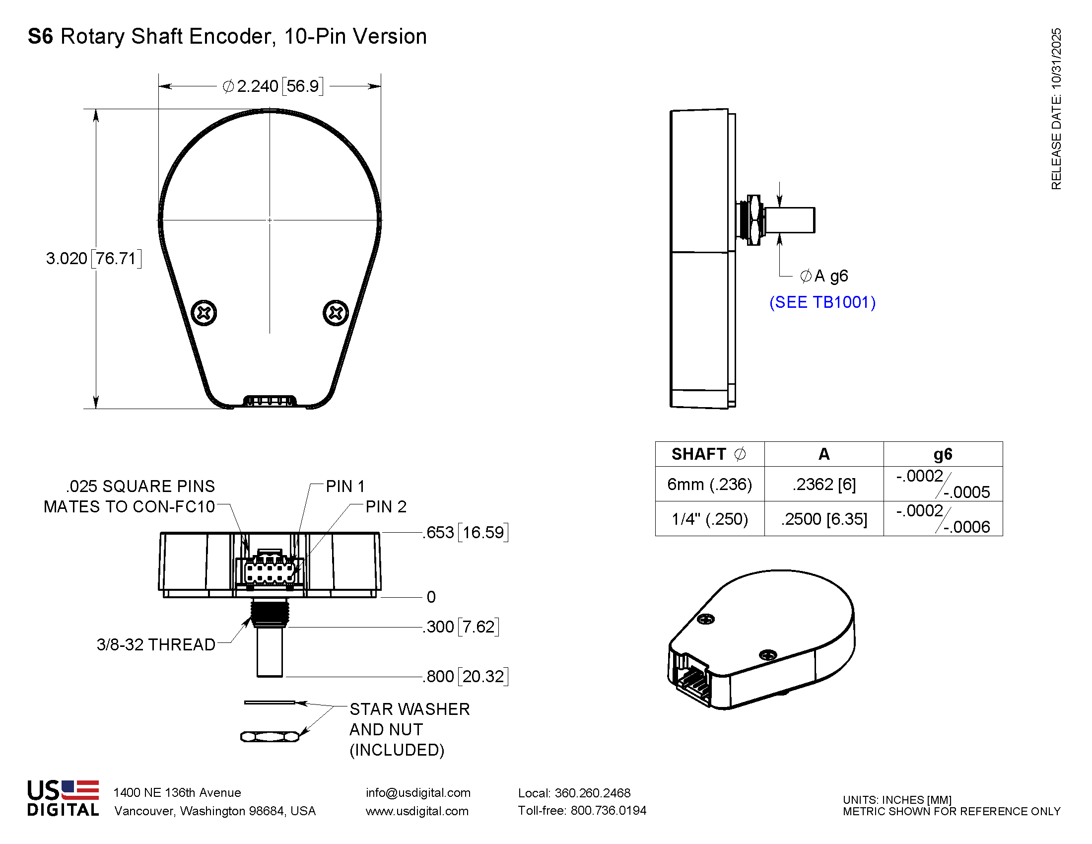
S6 Product Description
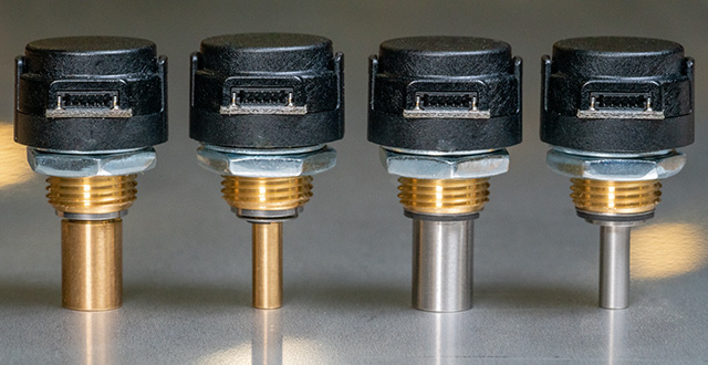
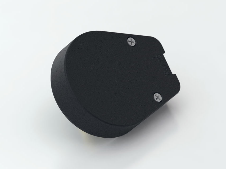
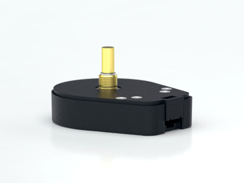
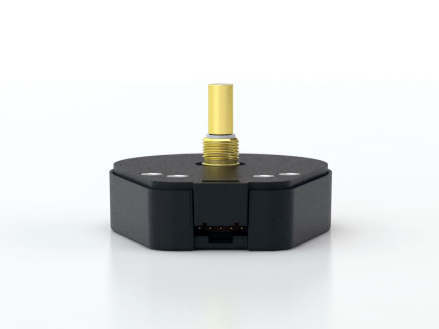
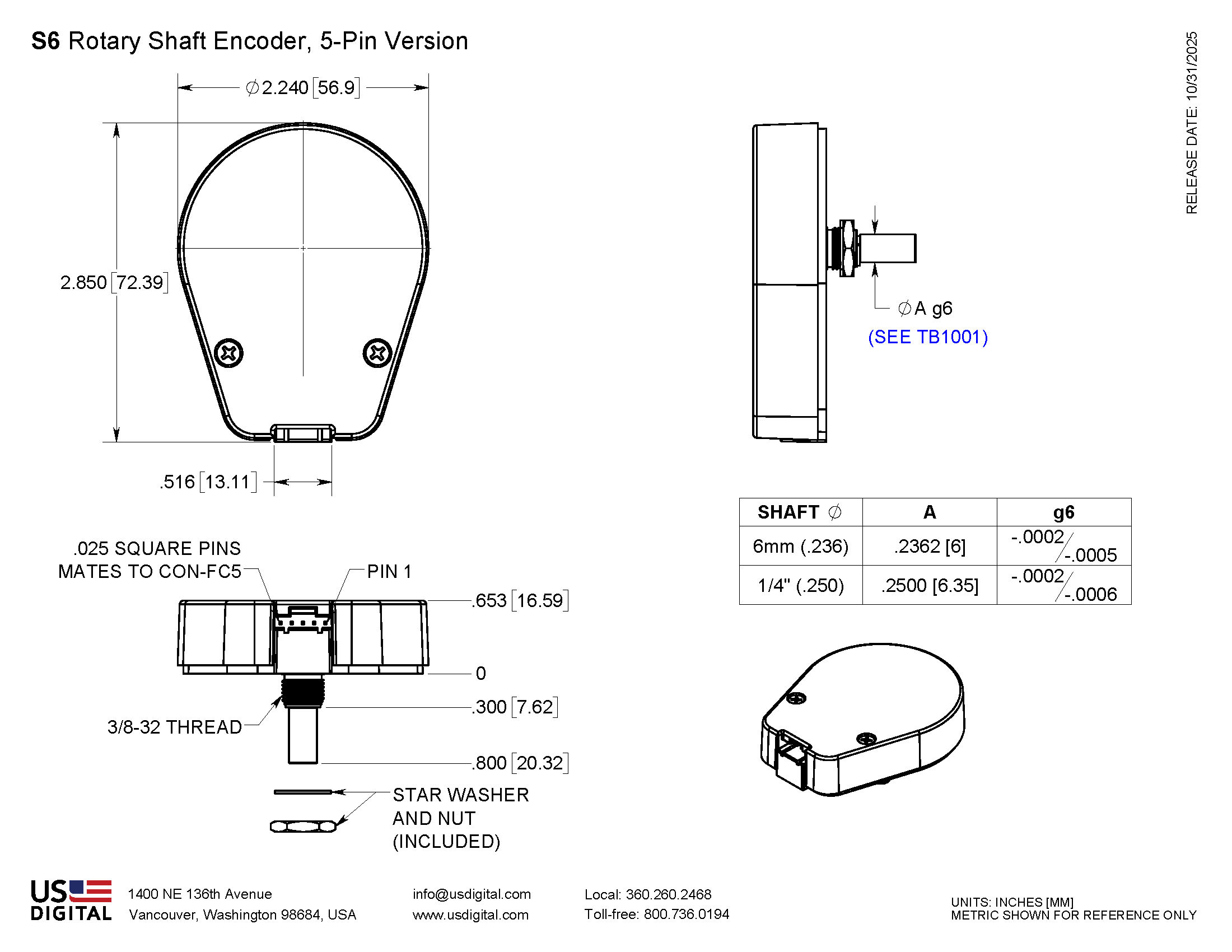
The S6 rotary shaft encoder converts shaft position or speed into a quadrature output signal. This rotary encoder delivers up to 40,000 PPR resolution in a glass-filled polymer housing. Available in 6 mm and 1/4 in. shaft sizes.
US Digital offers three different torque options for various uses:
Default (-D): sleeve bushing with higher damping for human interface applications.
Ball bearing (-B): miniature precision ball bearings suitable for high-speed applications.
Light static drag (-N): sleeve bushing with lower damping for low-speed applications.
This optical rotary encoder features three output options: single-ended, single-ended High-Voltage, and differential. For differential versions, the internal line driver (26C31) can source and sink 20mA at TTL levels. The recommended receiver is the industry-standard 26C32.
The S6 incremental encoder is designed for use with a secure latching connector. After you make your selections in the Product Configurator, compatible cables and connectors will be displayed below and must be ordered separately.
Product Specifications
ENVIRONMENTAL
Parameter
Value
Units
Operating Temperature, CPR < 2000
-40 to 100
C
Operating Temperature, CPR ≥ 2000
-25 to 100
C
Electrostatic Discharge
kV
Vibration (10Hz to 2kHz, sinusoidal)
20
G
Shock (6 milliseconds, half-sine)
75
G
MECHANICAL
PARAMETER
SLEEVE BUSHING
BALL BEARING
Max. Acceleration
250000 rad/sec²
250000 rad/sec²
Max. Shaft Speed (mechanical)
100 rpm (1)
10000 rpm (1)
Max. Shaft Torque
0.5 in-oz (D-option)
0.05 in-oz (B-option)
Max. Shaft Loading
2 lbs. dynamic
1 lb.
Bearing Life
> 1000000 revolutions
L10 = (19.3/Fr )³ *L10 = bearing life in millions of revs, andFr = radial shaft loading in pounds
Weight
Max. Shaft Runout
0.0015 in. T.I.R.
0.0015 in. T.I.R.
Max. Panel Nut Tightening Torque
20 in-lbs
20 in-lbs
Technical Bulletin TB1001 - Shaft and Bore Tolerances
Download
* Only valid with negligible axial shaft loading.
(1) The maximum speed due to electrical considerations is dependent on the CPR. See the EM1 and EM2 product pages.
PHASE RELATIONSHIP
B leads A for clockwise shaft rotation, and A leads B for counterclockwise rotation when viewed from the shaft side of the encoder.
SINGLE-ENDED OPTION
S option provides 5V TTL compatible outputs
Specifications apply over the entire operating temperature range
Typical values are specified at Vcc = 5.0Vdc and 25°C
For complete details, see the EM1 and EM2 product pages
PARAMETER
MIN.
TYP.
MAX.
UNITS
CONDITIONS
Supply Voltage
4.5
5.0
5.5
V
Supply Current
27
33
mA
CPR < 1000, no load
Low-level Output
0.5
V
IOL = 8mA max., CPR < 3600OL = 5mA max., CPR ≥ 3600
High-level Output
2.0
V
IOH = -8mA max., CPR < 3600OH = -5mA max., CPR ≥ 3600
Output Current Per Channel
-8
8
mA
CPR < 3600
Output Rise Time
110
nS
CPR < 3600
Output Fall Time
35
nS
CPR < 3600
DIFFERENTIAL OPTION
D Option provides differential line driver outputs
Specifications apply over the entire operating temperature range
Typical values are specified at Vcc = 5.0Vdc and 25°C
For complete details, see the EM1 and EM2 product pages
PARAMETER
MIN.
TYP.
MAX.
UNITS
CONDITIONS
Supply Voltage
4.5
5.0
5.5
V
Supply Current
29
36
mA
CPR < 1000, no load
Low-level Output
0.2
0.4
V
IOL = 20mA max.
High-level Output
2.4
3.4
V
IOH = -20mA max.
Differential Output Rise/Fall Time
15
nS
HIGH-VOLTAGE OPTION
H option uses a higher supply voltage and provides both single-ended and open-collector outputs
Single-ended outputs are 5V TTL compatible (same as S option). See Pin-out.
Specifications apply over the entire operating temperature range
For complete details, see the EM1 or EM2 product pages
PARAMETER
MIN.
TYP.
MAX.
UNITS
CONDITIONS
Supply Voltage
7.5
30.0
V
Supply Current, 24V power
8
10
mA
CPR < 500, no load
Open Collector "On" Resistance
2
ohms
Open Collector Sink Current
200
mA
Output Low Voltage
0.4
V
200 mA sink current
Open Collector Pullup Voltage
50
V
PIN-OUTS
5-PIN SINGLE-ENDED
10-PIN DIFFERENTIAL
10-PIN HIGH-VOLTAGE
Pin
Description
Pin
Description
Pin
Description
1
Ground
1
Ground
1
Ground
2
Index
2
Ground
2
Ground
3
A channel
3
Index-
3
Index- (open collector)
4
+5VDC power
4
Index+
4
Index+ (single-ended)
5
B channel
5
A- channel
5
A- channel (open collector)
6
A+ channel
6
A+ channel (single-ended)
7
+5VDC power
7
7.5-30V power
8
+5VDC power
8
7.5-30V power
9
B- channel
9
B- channel (open collector)
10
B+ channel
10
B+ channel (single-ended)
CON-FC5 .CON-FC10 .
PRODUCT CHANGE NOTIFICATIONS
Title
Date
Description
Download
Marketing/Insert - PCN 7058
11/04/2020
As part of our ongoing continuous improvement efforts, improvements are being incorporated into the E6, S6 and H6 series of Optical Encoders, including both single-end and differential output versions.
Download
Laser Marking - PCN 5253
6/17/2015
As part of our ongoing continuous improvement efforts, US Digital is changing the labeling/marking method for our E3, E6, H3, H6, S1, S2 and S6 products.
Download
EM1 & EM2 Update - PCN 4199
1/14/2014
Based on our continuous process improvement program, US Digital is changing the current marking method for our EM1 and EM2 encoder modules to a serialization method. This change will allow for each module to have a unique code; the current marking method is based on a date code system that includes all encoder modules produced within a specific week / year. The serialization system will be based on a hexadecimal system.
Download
EM1 LED Die - PCN 1016
2/7/2013
As part of US Digital's continual assurance of supply strategy, we have qualified additional sources for our LED die used in our EM1 encoder module, which in turn impacts all of the following products:
Download
Additional Information
Product Notes
Cables and connectors are not included and must be ordered separately.
For ordering information please configure the product and you'll see the Compatible Cables / Connectors section above.
US Digital® warrants its products against defects in materials and workmanship for two years. See complete warranty for details.
User Guides
Related
3D Model Downloads
Please
configure your product first
to download a 3D model. (Note: The formats below will become links if there are 3D models available.)
SolidWorks Format
IGES Format
Parasolid Format
STEP Format
Datasheet
Feedback
US Digital's mission is a commitment to quality and constant improvement. If you find an error to a product on this page, please let us know !
Save Your Configuration
Easily keep track of your custom part numbers
What is this feature?
While configuring your encoder, you can save your custom part number at any stage. This helps you keep track of multiple configurations without needing to start over or write anything down.
How does it work?
Click “Add This Configuration to Your List” after selecting your options.
Your saved part number will appear in a mini list below the configurator.
The list is stored locally in your browser and persists across product pages.
Enter a quantity to view default pricing.
What can you do with saved configurations?
When you're ready, visit the Saved Configurations List page to:
Review all saved part numbers
Fill out a form to send your selections to US Digital Customer Service
Receive follow-up to complete your order or get support
Why use it?
Save time by avoiding repeated configurations
Compare multiple part numbers side-by-side
Simplify communication with our support team
Got it!