MD3 Product Description
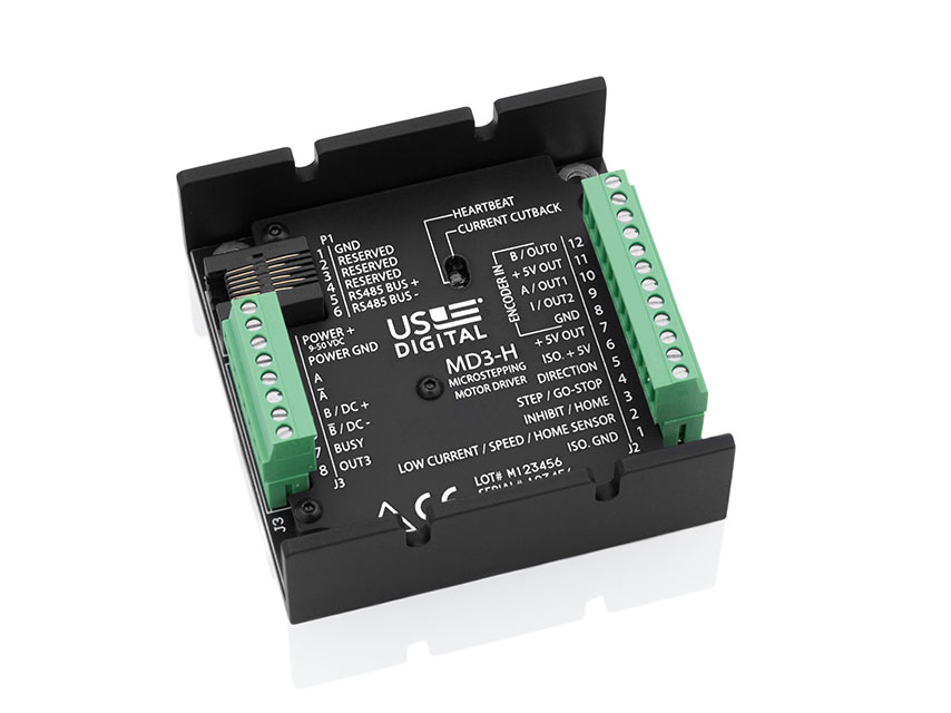
The MD3 is a stepper motor driver with an integrated motion controller capable of driving size 14 to 42 stepper motors from 2 to 256 microsteps per step. Peak motor currents are selectable from 0.5 to 7.0 amps per phase for the H-option version. The L-option provides selectable current from 0.05 to 1.8 amps per phase. A single supply voltage powers the MD3 from 9 to 50 VDC.
The MD3 can be configured and controlled using the open MODBUS RTU protocol over an RS485 bus. You can use US Digital's free MD3 Setup and MD3 Demo program to configure and control the drive using a graphical user interface. The MD3 can be configured to be mostly compatible with US Digital's existing MD2S-D and MD2S-P motor drivers . You can plug the pre-wired connector plugs from these existing products in as-is to the larger MD3 connectors. The register interface is published so that user can write their own control software for the MD3. Multiple MD3 units can be connected to the same RS485 bus since each unit can be assigned a unique device address. The MD3 has a built-in thermal shutdown to protect the drive from overheating and is firmware updatable by the end-user.
The MD3 has isolated step/direction or go-stop/direction digital inputs. In addition, the integrated motion controller allows Profile and Jog moves with user-specified acceleration, speed, and the number of steps. The drive also supports a switch or incremental encoder index home cycle with pre-and post- home offset movement options. The Home cycle can run automatically on startup after a programmable delay or on command. The MD3 can start all motion commands using the isolated digital input lines in addition to MODBUS commands.
Product Specifications
MECHANICAL
Weight
4.59 oz. (with mating connectors)
Size
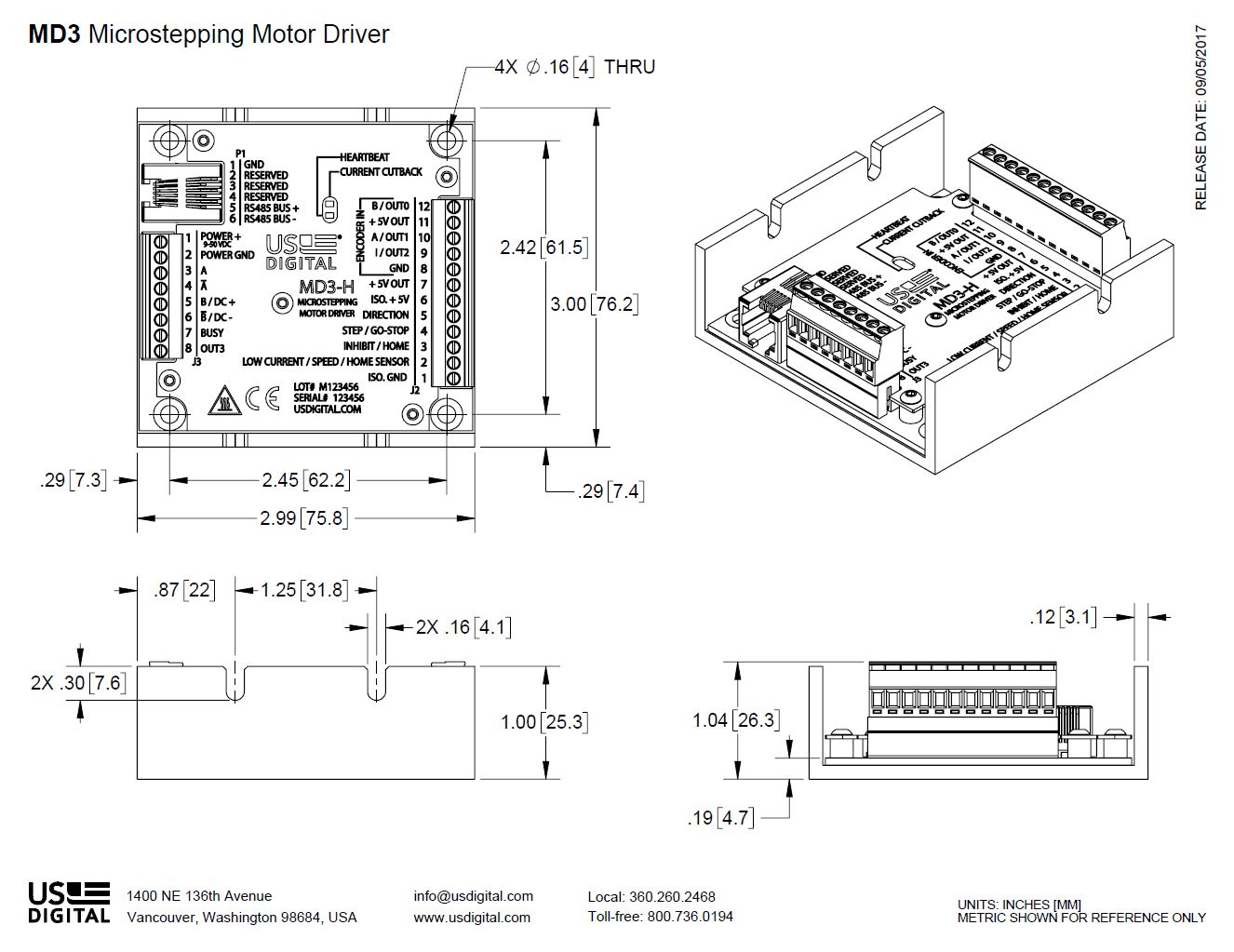
2.99" x 3.00" x 1.04"
Mounting Pattern
Use 2 to 4, #4 or #6 machine screws
Case Material
Black anodized aluminum
Terminal Plug Wire Gauge
14-28 AWG
Operating Temperature
-25C to 70C (7A motor current)
ELECTRICAL
PARAMETER
MIN.
TYP.
MAX.
UNITS
Power Supply Voltage
9
24
50
V
Power Supply Current
Isolator Supply Voltage
2.5
5.0
5.5
V
Isolator Supply Current
6.1
9.2
mA
+5VDC Power Out Voltage
4.75
5.0
5.25
VDC
+5VDC Power Out Current
100
mA
Peak Output Phase Current (selectable)
Step Frequency
Logic Low Input Voltage (J2 pins 2, 3, 4, 5, 9, 10, 12)
0
0.8
V
Logic High Input Voltage (J2 pins 2, 3, 4, 5, 9, 10, 12)
2.0
5.0
V
Input Leakage Current (J2 pins 2, 3, 4, 5, 9, 10, 12)
-10
10
µA
Logic Low Output Voltage (J2 pins 9,10,12 - output mode), 3 mA load
0
0.4
V
Logic High Output Voltage (J2 pins 9,10,12 - output mode), 2 mA load
3
V
Open drain FET voltage rating (J3 pins 7,8)
30
V
Open drain FET current (J3 pins 7,8)
1
A
Electrostatic Discharge, IEC 61000-4-2
± 8
kV
MOUNTING
The MD3 package consists of a 0.12" thick anodized aluminum extrusion. Use 2 or more screws in any of the four 0.16" diameter mounting holes. Typical mounting screw sizes are #4 or #6.
CONNECTORS
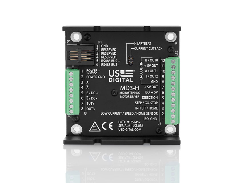
The MD3 has an 8 pin and 12 pin pluggable screw terminal connectors and a 6 position RJ11 connector. Make sure that the terminal blocks are wired to the MD3 correctly before applying power. Do not allow the motor leads to short each other, to ground or to power as this could damage the MD3.
CONNECTOR J2 PIN DESCRIPTION
1
Isolator GND input (must be connected to J2 pin 8 or external GND)
2
LOW CURRENT/SPEEDSEL/HOME SENSOR input (isolated, 5k pullup)
3
INHIBIT/HOME input (isolated, 5k pullup)
4
STEP or GO-STOP input (isolated, 5k pullup)
5
DIR input (isolated, 5k pullup)
6
Isolator +5V input (must be connected to J2 pin 7 or external +5V source)
7
+5V out
8
GND
9
Encoder Index or digital I/O bit
10
Encoder A or digital I/O bit
11
+5V out
12
Encoder B or digital I/O bit
The main motion control inputs of the MD3 are on J2 pins 2,3,4,5. These pins are electrically isolated to prevent noise from the motor drive from crossing over to the rest of the system. The isolator requires a separate 2.5V to 5.5V power supply on J2 pin 1 and pin 6. If a separate power supply is not available, the isolator can be powered by +5V generated by the MD3 on J2 pins 7 and pin 8, at the expense of noise isolation. All isolated logic inputs on J3 are pulled to the high (inactive) state by 5 kΩ resistors.
CONNECTOR J3 PIN DESCRIPTION
1
Power supply input, 9-50 VDC
2
GND
3
Stepper Phase A
4
Stepper Phase A-
5
Stepper Phase B (DC Motor +)
6
Stepper Phase B- (DC Motor -)
7
BUSY output (open drain FET to GND). Output is switched to GND when the motor is moving, or the drive is in thermal shutdown
8
Digital output bit (open drain FET to GND)
CONNECTOR P1 PIN DESCRIPTION
1
GND
2
Reserved
3
Reserved
4
Reserved
5
RS485 Bus+
6
RS485 Bus-
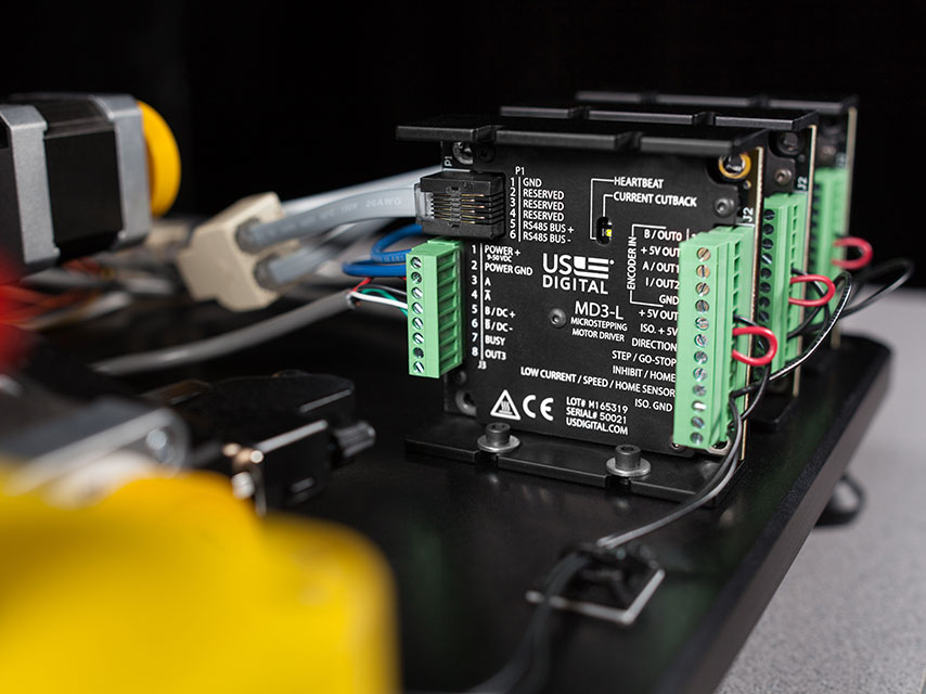
To maintain close compatibility with the previous MD2S driver (which has 6/8 pin connectors), the pinout of the MD3 8/12 pin connectors is designed so that prewired MD2S screw terminal plugs can be plugged directly into the MD3 as shown below and function the same.
LEDS
State
Heartbeat LED (Green, D6)
Current Cutback LED (Red, D5)
Boot-up
Both LED's will flash on/off twice if the MD3 registers were loaded without errors from EEPROM. If there are errors, the red LED will flash rapidly on/off for 5 seconds and the MD3 registers will be initialized with default values. The drive will then enter the "Startup delay" state
Startup Delay
There is a built in 2.5 second startup delay before the motor current is turned on and the drive responds to commands. Additional delay can be configured using the MD3 Demo program or with serial commands. During the Startup delay period, the Heartbeat and Current Cutback LED's will flash alternately. When this state ends, the drive will enter the "Normal operation" state.
Normal Operation
Flashes once every ~1.5 seconds
Off
Currrent Cutback
Flashes once every ~1.5 seconds
On
Thermal Shutdown
Off
Flashes once every ~1.5 seconds
POWER SUPPLY
High performance stepper motors are designed with minimum winding resistance and inductance to minimize heat loss and maximize high speed torque. Motor torque at low speeds is directly proportional to the current setting and is not affected by power supply voltage or microstepping resolution. Torque remains relatively constant until it starts falling off at a speed threshold proportional to the power supply voltage.
POWER DISSIPATION
The MD3 can safely dissipate a sufficient amount of heat in free air for motor currents of 7A or less. The following table shows some typical housing temperatures after 24 hours of continuous operation without any additional heat sink. The metal housing of the MD3 can be kept cooler if it is mounted to a heat-sinking metal surface or if the drive is operated intermittently.
Test Condition
Typical Equilibrium Housing Temperature
@24C ambient, free air
@70C ambient, moving air
24V supply, 3.5A motor current
37C
76C
24V supply, 7A motor current
55C
85C
50V supply, 3.5A motor current
46C
81C
50V supply, 7A motor current
71C
94C
Be sure that the motor screw terminal connections on J3 are tight. Loose connections have a higher resistance which may cause excessive heating at the connector as the MD3 tries to maintain the peak phase currents at the specified levels.
PARAMETER AND CONTROL SETTINGS
Unlike the MD2S, which uses jumpers and DIP switches for configuration, all configuration of the MD3 drive occurs over an RS485 serial port on P1. A USB to RS485 adapter (not included) is needed to connect a PC to the MD3. The serial port uses the Modbus RTU protocol. Modbus RTU is a simple, register-based command/response protocol. All MD3 settings such as phase current, microstepping, etc. are stored in thirty-two flash memory registers in the MD3. The MD3 User Guide gives full details on register read and write commands needed to configure the product. In addition to configuration, the serial port can also be used to send motion commands such as Move, Jog, Home, etc. so a host such as a PLC can control the MD3.
The default register settings are listed in the MD3 User Guide. The default serial communication settings are: Modbus device address = 1, 9600 bps, 1 start bit, 8 data bits, even parity, 1 stop bit. The default stepper motor settings are 1A current and 1/8 microstep.
US Digital provides the free MD3 Setup and MD3 Demo programs that provide a graphical user interface to the internal registers. The MD3 Setup program presents a simple interface for customers that want to configure the MD3 to function as US Digital’s existing MD2S-D or MD2S-P product. This program only allows the user to set options available on the MD2S-D or MD2S-P. The MD3 Demo program gives the user full control of all the features of the MD3.
DC MOTOR PWM MODE
The MD3 has a PWM mode that can be used for brushed DC motor speed control. See the MD3 User Guide for more information
FIRMWARE REVISIONS
PRODUCT
REV.
RELEASE DATE
NOTES
MD3
4
9 Feb 2021
Current firmware
The "Tshutdown" bit of Modbus Motion Control Register (0x11) is now renamed to "Fault". A Fault will stop all running motion commands. Faults can be cleared by writing to a bit in the Motion Control Register or activating the INHIBIT/HOME input (J2 pin 3).
Added INHIBIT_MODBUS_MOTION mode to J2 pin 3 that will stop all running motion commands, block all modbus commands (except for enable/disable) and leave motor current enabled. This allows the drive to be inhibited without losing its position since the motor current remains on.
Reduced audible motor noise in some circumstances and improved tolerance to drive current faults.
Download firmware version 4. Download MD3 User Guide version 1.5. download PCN-7114
MD3
3
8 Jan 2019
Current firmware
Additional Information
User Guides
Software
Related
Press Releases
3D Model Downloads
Please
configure your product first
to download a 3D model. (Note: The formats below will become links if there are 3D models available.)
SolidWorks Format
IGES Format
Parasolid Format
STEP Format
Datasheet
Feedback
US Digital's mission is a commitment to quality and constant improvement. If you find an error to a product on this page, please let us know !
Save Your Configuration
Easily keep track of your custom part numbers
What is this feature?
While configuring your encoder, you can save your custom part number at any stage. This helps you keep track of multiple configurations without needing to start over or write anything down.
How does it work?
Click “Add This Configuration to Your List” after selecting your options.
Your saved part number will appear in a mini list below the configurator.
The list is stored locally in your browser and persists across product pages.
Enter a quantity to view default pricing.
What can you do with saved configurations?
When you're ready, visit the Saved Configurations List page to:
Review all saved part numbers
Fill out a form to send your selections to US Digital Customer Service
Receive follow-up to complete your order or get support
Why use it?
Save time by avoiding repeated configurations
Compare multiple part numbers side-by-side
Simplify communication with our support team
Got it!