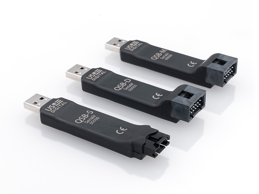
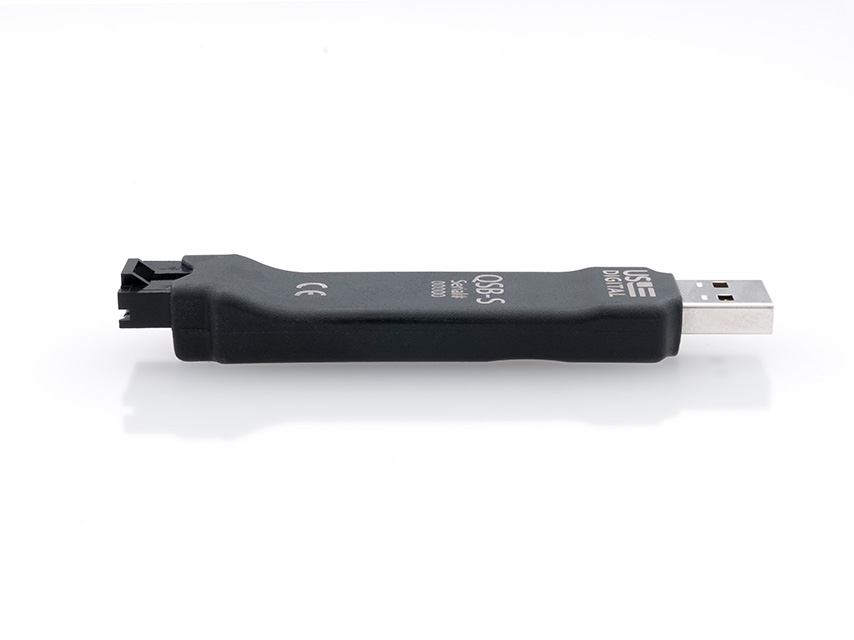
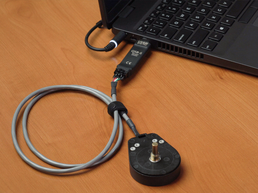
QSB Product Description The QSB is a low-cost USB data acquisition device. The QSB-S and QSB-D count quadrature and index signals from incremental, PWM, and analog encoders. The QSB-M provides digital I/O and acts as a 1-channel stepper/motor controller.
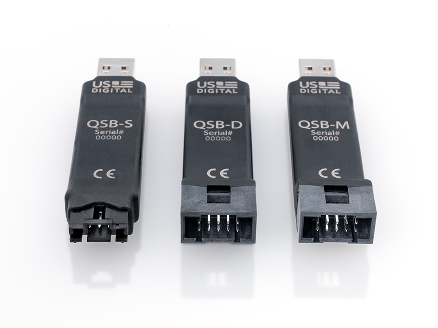
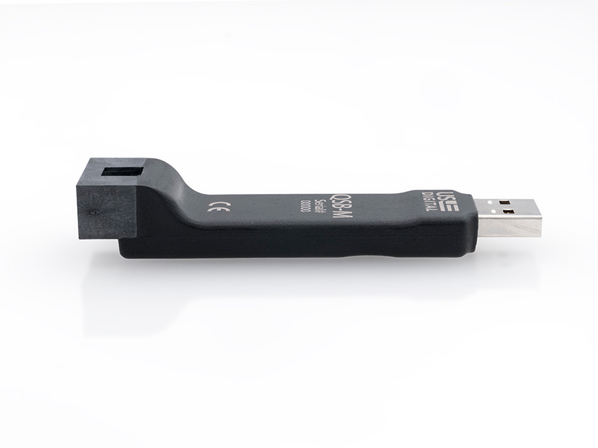
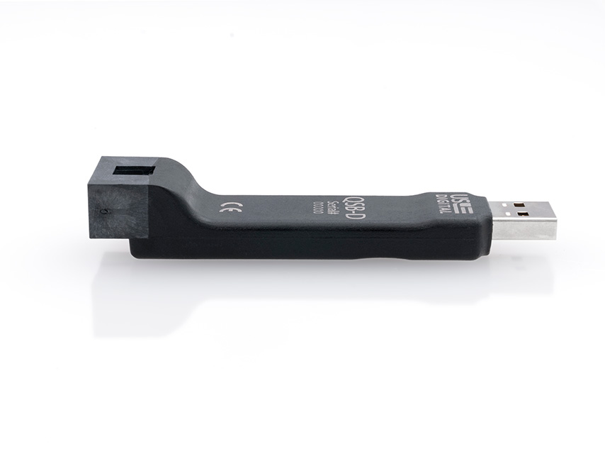
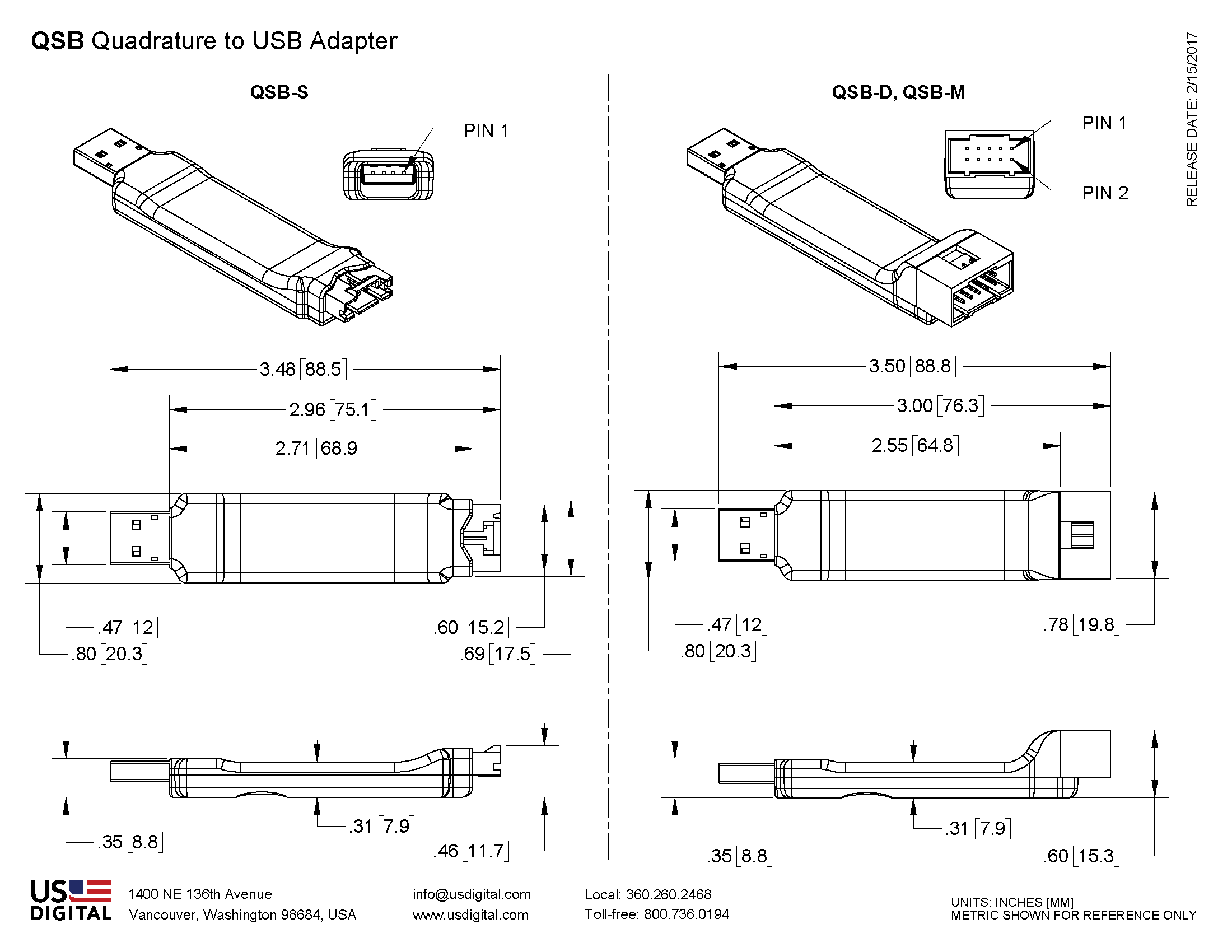
QSB-S - One single-ended quadrature, PWM, or Analog encoder interfaceQSB-D - One differential quadrature, PWM or Analog encoder interface and 1-bit of digital I/OQSB-M - One single-ended quadrature, PWM or Analog encoder interface; 4-bits of digital I/O or 2-bits of digital I/O and 1-channel stepper motor control (step/direction)
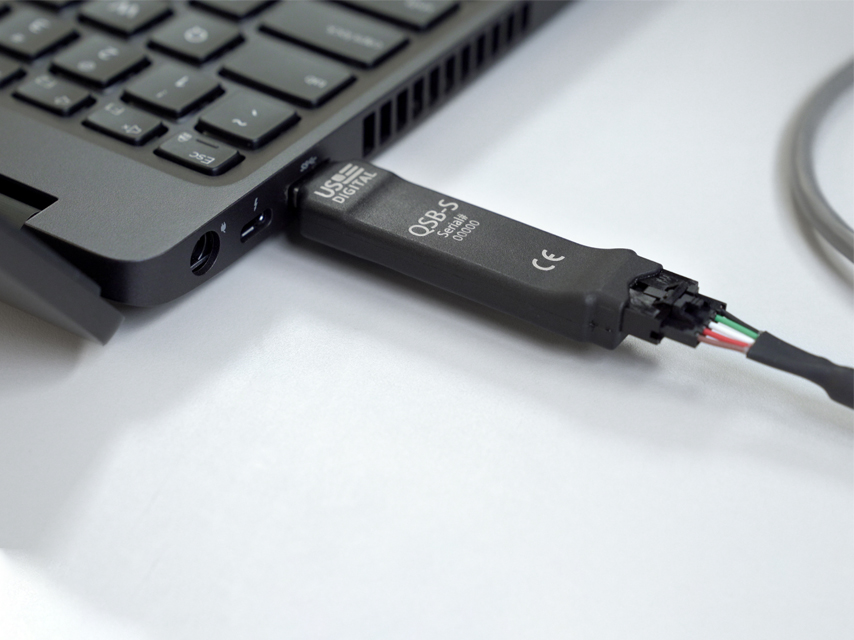
The QSB plugs into any USB (Type A) port on a Windows or Linux machine and is bus-powered. US Digital provides free software, examples, and documentation needed to use the QSB. The QSB appears as a COM serial port to the PC, so any application that can read/write the COM port can be used to control the QSB.
The QSB-S and QSB-D can be used with the “QuickCheck ” app to verify the CPR of an encoder with index quickly.
WARNING: This product can cause exposure to substances, such as phthalate plasticizers , known to the State of California to cause cancer and reproductive harm. For more information, go to oehha.ca.gov/proposition-65 .
Product Specifications
ENVIRONMENTAL
PARAMETER
MIN.
MAX.
UNITS
Operating Temperature
0
70
C
Electrostatic Discharge,
ELECTRICAL
PARAMETER
MIN.
TYP.
MAX.
UNITS
Supply Voltage (1)
4.75
5.00
5.25
V
Supply Current (QSB device only)
52
mA
Supply Current (External devices) (2)
450
mA
(1) Voltage is regulated by USB port
(2) USB port capable of supplying 500mA maximum
PIN-OUTS
QSB-S Pinout
Pin 5-Pin Connector
1
Ground
2
Index
3
A Channel or EAN0 or PWM0
4
+5 Volts
5
B Channel
Notes:
Pin 3 EAN0 is an A/D input designed for the MAE3-A10 and MA3-A10 analog output encoders. It can be used as a generic 10-bit A/D input (0-5V range).
Pin 3 PWM0 is a pulse width modulation input designed for the 10 or 12-bit PWM output of the MA3/MAE3 encoders
QSB-D, QSB-M Pinout
Pin 10-pin 10-pin
1
Digital I/O
Digital I/O
2
Ground
Ground
3
Index-
Digital I/O
4
Index+
Index
5
A-/PWM0-
Digital I/O
6
A+ or EAN0 or PWM0+
A or EAN0 or PWM0
7
+5 Volts
+5 Volts
8
No connection
+5 Volts
9
B-
Digital I/O
10
B+
B
Notes:
Pin 6 EAN0 is an A/D input designed for the MAE3-A10 and MA3-A10 analog output encoders. It can be used as a generic 10-bit A/D input (0-5V range).
Pin 6 PWM0+/PWM0- is a differential pulse width modulation input designed for the 10 or 12-bit PWM output of the MA3/MAE3 encoders.
ENCODER INTERFACE (QSB-D, QSB-M, QSB-S)
Quadrature Encoder Input Frequency
0
6
MHz
PWM Encoder Input Frequency (1)
250
1000
Hz
Encoder Single-Ended Interface
-Low Input
-0.5
2.1
V
-High Input
2.8
5.5
V
Encoder Differental Interface
-Differential Voltage
0.2
5.5
V
-Input Voltage Range
-0.5
5.5
V
Analog Encoder Input
-Voltage Range
0
5
V
-DC Input resistance
4.8
6.3
9
kOhm
-Bandwidth
0
3000
Hz
(1): The PWM mode is designed specifically to operate with US Digital's MA3/MAE3. The EA-D-L-10 interface device is required for use with the QSB-D.
DIGITAL I/O (ALL VARIANTS)
PARAMETER
MIN.
TYP.
MAX.
UNITS
Digital Input Voltage
0
5
24.5
V
Positive-going Input Voltage Threshold
1.5
2.5
V
Negative-going Input Voltage Threshold
0.83
1.82
V
Input Voltage Hysteresis
0.33
1.1
V
Digital High Output Voltage (Note 1)
4.5
4.7
5.0
V
Digital Low Output Voltage (Note 1)
0
0
V
Note 1: Output can be externally pulled up to 24V through a load if desired. Open drain MOSFET pulldown capable of 1.0 A max. continuous current. See digital output port circuits below. When driving inductive loads, add an external diode to protect the QSB from damage caused by large voltage transients.
Digital Input Port Circuit:
Digital Output Port Circuit:
STEPPER MOTOR CONTROL (QSB-M ONLY)
The speed and direction of a single stepper motor can be controlled using the QSB-M in conjunction with a stepper motor driver, such as the US Digital MD3. Two of the four digital I/O port pins can be configured to have motor step/direction functionality or normal digital I/O.
See the QSB Command List document for detailed information on the QSB's motor control commands.
SOFTWARE FIELD UPGRADE
The QSB firmware can be easily upgraded using the "QSB Firmware Updater " program that is available on the QSB Software page. There may be periodic upgrades to the QSB firmware that can be loaded as needed by a customer. The firmware upgrades typically take less than 30 seconds.
PRODUCT CHANGE NOTIFICATIONS
Title
Date
Description
Download
PCN 6938 - QSB Product Marking
2/17/2020
This PCN is a formal notification that US Digital is implementing a product marking change for the Quadrature to USB Adapter series of products. The new marking will be used across all models, including the QSB-S, QSB-D and QSB-M. The new marking is designed to improve readability for customers while the device is plugged into a computer and to include the CE mark. US Digital recently added the CE mark to the QSB series, meaning these products are now available to ship worldwide.
Download
PCN 4464 - CE - RoHS
6/30/2014
US Digital is aware of the increasing attention to world-wide environmental regulations, specifically with regard to the need for hazardous substance restrictions in electronic components and systems. As of July 10th, 2014 US Digital will now be CE Marking certain products inline with compliance under RoHS Directive (2011/65/EU). In order to achieve RoHS Compliance, the products will not contain more than the acceptable levels of the listed restricted substances within the RoHS 2011/65/EU directive.
Part Numbers Affected:
ED3
USB4
QSB
SEI-USB
MD2S
PS-5, PS-12, PS-24, PS-48 (Power Supplies)
PE
For the part numbers listed above, US Digital cannot confirm that they meet Low-Voltage and EMC Directives and for that reason US Digital cannot support shipping those products / product families into the CE required countries (For Example countries in the EU). Those products can still be shipped to Non-CE required countries with a Statement of Material Conformance to the RoHS Directive 2011/65/EU, in place of a RoHS Compliance Declaration.
Download
Additional Information
Product Notes
Cables and connectors are not included and must be ordered separately.
US Digital® warrants its products against defects in materials and workmanship for two years. See complete warranty for details.
Datasheets
User Guides
Software
Related
Feedback
US Digital's mission is a commitment to quality and constant improvement. If you find an error to a product on this page, please let us know !
Save Your Configuration
Easily keep track of your custom part numbers
What is this feature?
While configuring your encoder, you can save your custom part number at any stage. This helps you keep track of multiple configurations without needing to start over or write anything down.
How does it work?
Click “Add This Configuration to Your List” after selecting your options.
Your saved part number will appear in a mini list below the configurator.
The list is stored locally in your browser and persists across product pages.
Enter a quantity to view default pricing.
What can you do with saved configurations?
When you're ready, visit the Saved Configurations List page to:
Review all saved part numbers
Fill out a form to send your selections to US Digital Customer Service
Receive follow-up to complete your order or get support
Why use it?
Save time by avoiding repeated configurations
Compare multiple part numbers side-by-side
Simplify communication with our support team
Got it!