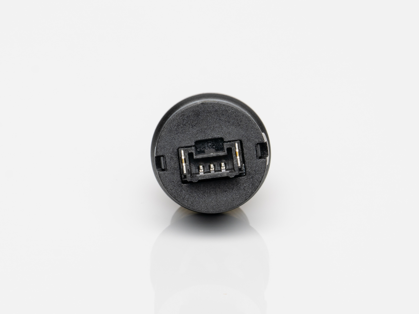
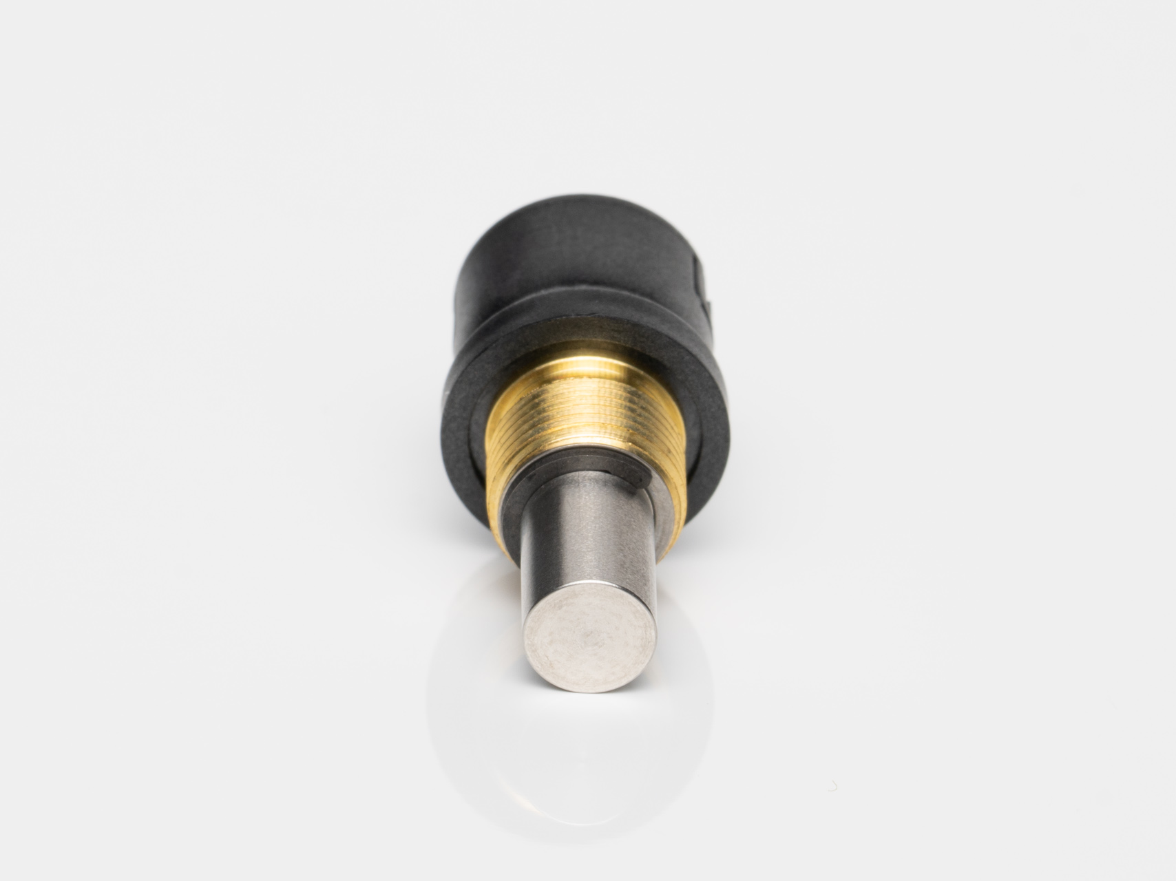
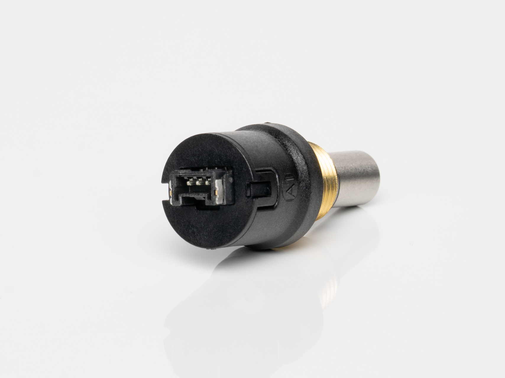
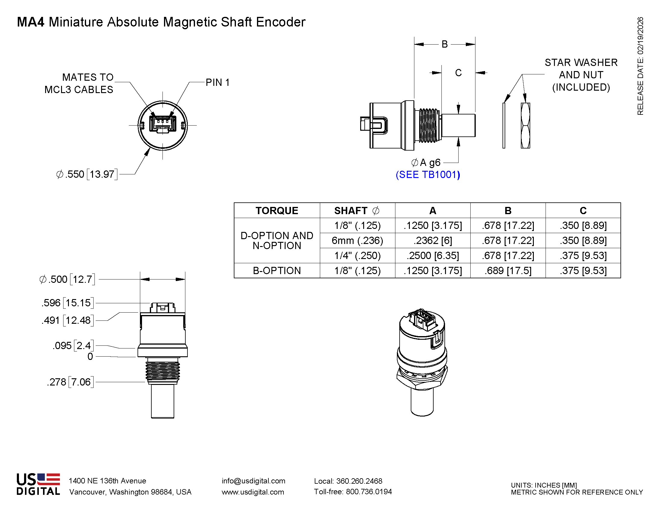
MA4 Miniature Absolute Magnetic Shaft Encoder
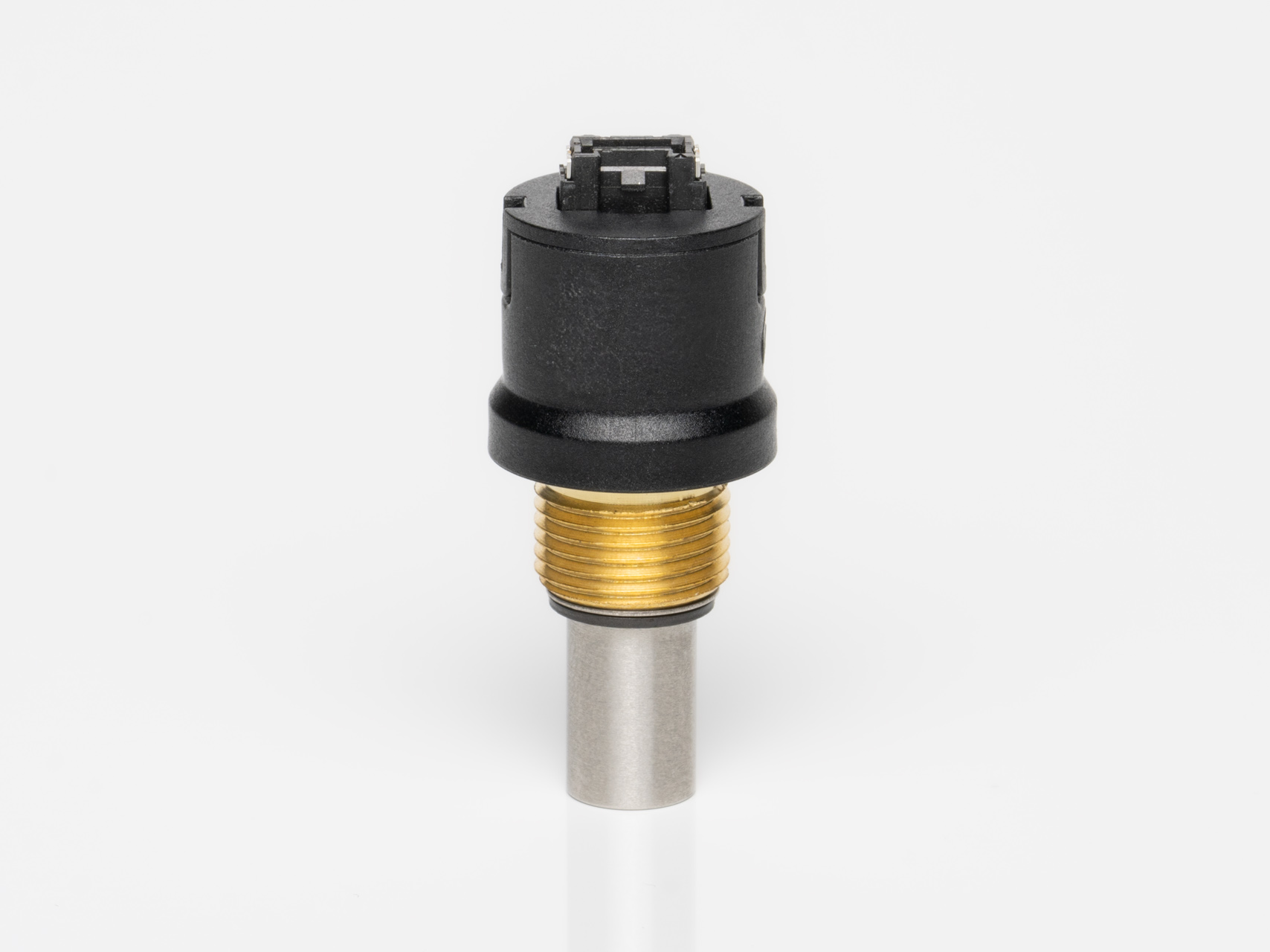
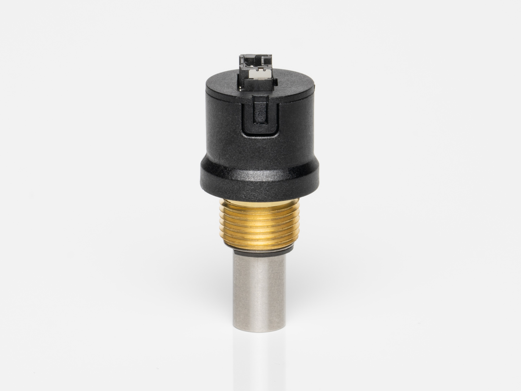
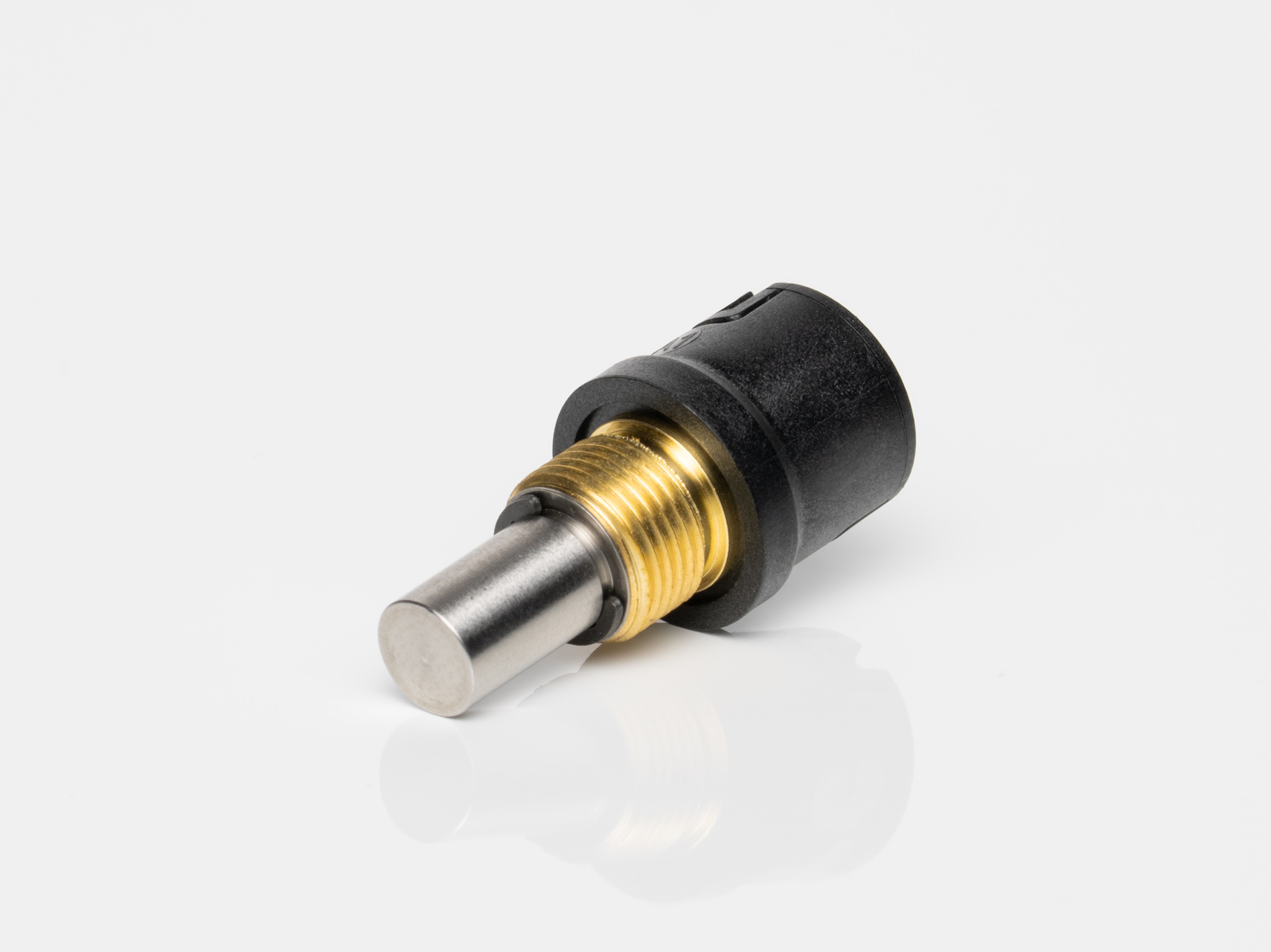
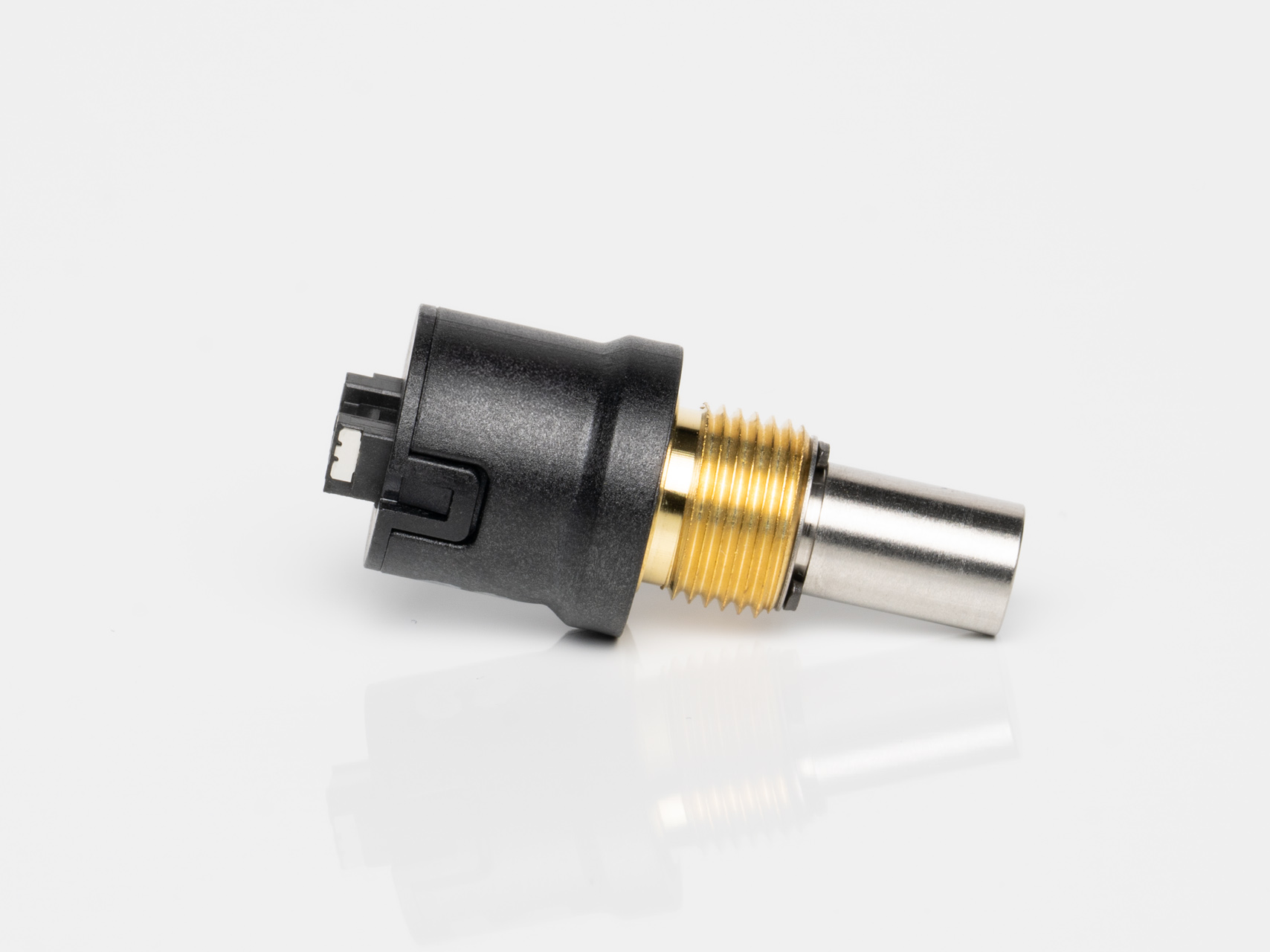
MA4 Features
- 12-bit Analog or PWM output
- Miniature size (0.55 in. diameter)
- -40C to 125C operating temperature range
- Latching Connector
- Three shaft torque options*
See more info below
Configure the MA4

40 percent smaller than our S4T, but with higher resolution. Up to 4,096 CPR before quadrature and available with index.

We have now updated and expanded our kit encoder assembly videos. Assembly videos for the E2, E3, E5, E6, E4T, and E8T encoder are now available.

We've been making encoders and motion control products for over 40 years. Discover why our history, culture, and devotion to our customers' success makes us unique in the manufacturing world.
See more info below
Configure the MA4