


What is a Motor Encoder?
A Motor Encoder is a rotary encoder designed for installation onto a motor shaft, typically a motor tail shaft. They can be installed on other shafts in a mechanical system.
What do Motor Encoders do?
Motor encoders translate the motor shaft movement into an electrical signal. This output can be used to determine shaft angle, shaft speed, and shaft direction.
Why are Motor Encoders used?
Encoders act like a GPS for your motor. Depending on the encoder used, you can know the angle of the motor shaft, the speeds at which it rotates, and the direction it is rotating.
Having this information can allow a control system to send a command to the motor or other device to make sure it does what you need in your application—like keeping a flow rate of liquids in a pump constant, moving a robotic arm to the proper angle, or cutting a cable at the proper length.
How do Motor Encoders work?
They consist primarily of a disk and a sensor, though depending on the design they may also include an emitter like an LED. As the disk rotates, the sensor provides an output proportional to the movement of the shaft.
Optical Motor Encoder
These encoders have a specially patterned disk rotating between an LED and a detector sensor—reporting is based on when the LED light is seen by the sensor and when it is not for transmissive encoders. For reflective encoders, the light beam bounces off the reflective disk to the photodetector, producing the same results.

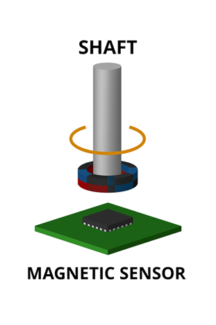
Magnetic Motor Encoder
This encoder type has a magnet on a shaft whose movement is monitored by a magnetic sensor—reporting is based on the change in the magnetic field as the magnet rotates.
Capacitive Motor Encoder
These encoders have a specially patterned rotor which is monitored by a stationary capacitive plate commonly called a stator—reporting is based on the capacitance change between the rotor and the stationary plate as the rotor rotates.

What is the difference between an Incremental Motor Encoder and an Absolute Motor Encoder?
Rotary incremental encoders
These encoders provide an output indicating the changes in the shaft movement. In other words, if all you need to do is monitor the speed of the shaft, or the direction the shaft is turning, or the relative distance turned, an incremental encoder is a great choice. If the encoder has an index, it can also provide information as to the number of turns the encoder has rotated or provide a fixed starting position for distance measurements. Without an index, incremental encoders lose position data after a power cycle, until the encoder (with an index) performs a homing cycle. However, a power cycle would also cause the encoder to lose any information about the number of turns the encoder has rotated.
Absolute rotary encoders
This type of encoder can do everything an incremental encoder can do, plus, as each resolvable position provides a unique output, even after a power cycle, the output of the encoder provides the information as to the angle of the shaft. Multi-turn encoders add one more piece of information, keeping track of the number of turns the encoder has rotated. even after a power cycle.
What kind of output do Motor Encoders produce?
Quadrature
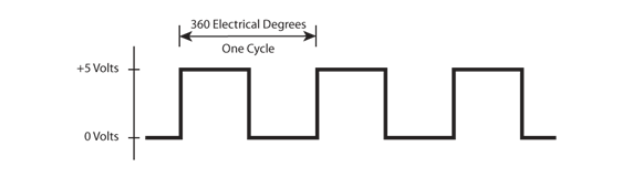
The most common encoder output is referred to as quadrature output. The term quadrature is used because the signals of the two main channels are offset by 90º or ¼ of a complete cycle. Below are several interface types using quadrature.
Incremental Output Interface Types
Single-Ended
The quadrature output is a square wave signal produced on two channels typically referred to as Channels A & B. As stated above, these channels are offset by 90º electrical degrees which allows for direction detection also.
These encoders can also have an Index channel, often referred to as channel I or Z, which provides an output just one time in the rotation of the disk.

Open Collector (NPN)
A drawing of the signal for this output would look identical to the one above. The difference is that an open collector output doesn’t send out its own voltage but instead relies on the connected device or system to complete the signal. An example of this type of output is when a 5VDC encoder provides an output of 24VDC.
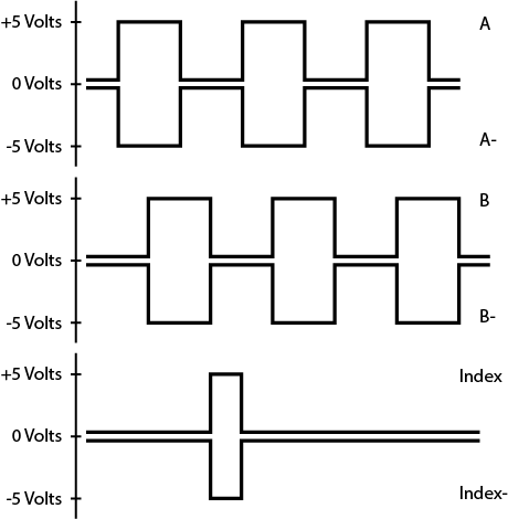
Differential Output
A differential encoder output provides a quadrature signal and a complementary signal, which is the inverse of the main signal. This larger signal differential makes it an excellent choice for long cable runs and for installations in an electrically noisy environment. It does require a differential receiver.
Absolute Output
An absolute output can be an analog voltage or pulse width modulation (PWM) where the output varies in relation to the 360º rotation of the encoder/shaft—lowest before 1º and highest after 359º.
Absolute encoders also often use serial interfaces which include such protocols as SEI, SSI, BiSS-C, Profibus, etc.
 |
 |
| Drawing of an Analog Absolute Encoder Output | Drawing of PWM Absolute Motor Encoder |
Commutation Output
Encoders with a commutation output provide UVW signals allowing the control system to determine the rotor’s position and properly sequence current delivery to the motor windings. BLDC motors need commutation output to operate at the proper speeds.
Which Kinds of Motors Use Encoders?
Note – Servo motors are typically BLDC motors with some brush style motors being used as well. A stepper motor is a specialized version of a BLDC motor and some applications use stepper motors as servo motors in simple low cost servo systems.
Servo Motors
It is estimated that over half of all motor encoders are used on Servo Motors. They demand high-resolution feedback from encoders to hit exact positions. Application examples include CNC machines, robots and surgical devices.
AC Motors
AC Induction Motors are the second most common motor on which encoders are used. Because of the environment in which these motors are often installed—Motor Encoders used in these applications may be required to tolerate more vibration and shock. Application examples include industrial pumps, power conveyers, and maybe even the high-powered blender in your kitchen.
DC Brushed Motors
Often due to their low cost and simple design, DC Brushed Motors are used with encoders in simple automation, electric scooters, and other smaller electric vehicles.
Stepper Motors
Hybrid Stepper Motors probably comprise another 20% of motor encoder applications. Encoders can be used to monitor the movement—make sure it moved the correct distance, or it can be used to report that information to a controller to close the loop and modify the position. Application examples are labeling machines, automated arms, textile machines, and semiconductor equipment.
Brushless DC Motors (BLDC)
BLDC motors provide good efficiency, longevity, and high performance. Adding an encoder can provide position control, speed regulation, and error detection. Some encoders used with BLDC motors can also provide a commutation output which monitors rotor position used to determine which coils to energize. Application examples include drones, gate operators, medical devices, and HVAC.
Linear Motors
Linear Motors can use several of the above motor technologies, but they would require a linear encoder—which is not traditionally thought of as a “Motor Encoder” as motor encoders are typically, rotary encoders.
How do Motor Encoders Mount to a Motor?
While a shafted encoder can be mounted to a motor via a coupler, besides being less expensive, it is simpler and will typically last longer if an encoder is connected directly to a motor shaft.
Encoder Kits
Motor encoders, which are sometimes referred to as kit encoders, encoder kits, or modular encoders, are designed for easy installation to a motor with standard bolt hole patterns. Many motor manufacturers provide motors with motor encoders already installed on them—some refer to those as encoder motor sets.

Hollow bore
Also known as hollow shaft encoders, they mount directly to motors, but as they have their own bearing, a flexible coupler is required to tether the encoder base to the motor or other mounting surface. This encoder type is often used in an environment where it might be subjected to some abuse. Typical applications include use in manufacturing environments, dynamometers, and printing presses.

Conclusion
This is a high-level overview of motor encoders for a more detailed look, check out our white papers like this one, our corporate video, our educational videos, our Glossary, or our FAQ's. But, more importantly, if you need assistance choosing an encoder for your next project, we have a great team ready to assist you in any way you like.
Technical Support 360.397.9999 support@usdigital.com
Sales Support 360.260.2468 sales@usdigital.com
More in News
Stay up to date
Sign up for our newsletter to stay up to date with our product updates, blog posts, videos and white papers.