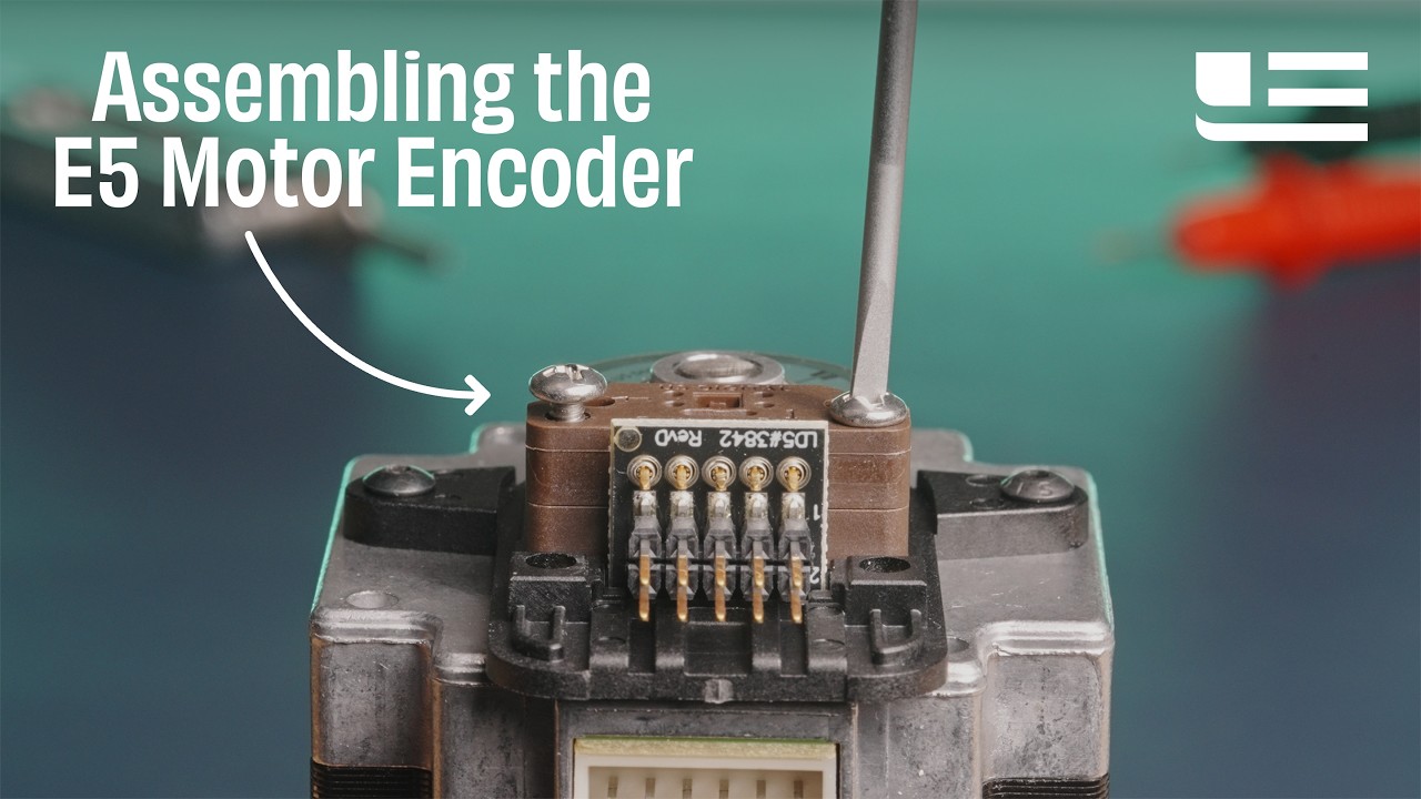
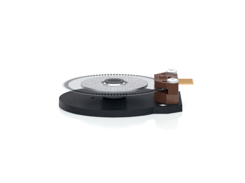
US Digital Motor Encoder E3 Description The US Digital E3 motor encoder mounts directly to a motor or other rotating shaft. This optical encoder features a rugged, glass-filled polymer housing and is designed for easy installation and removal.
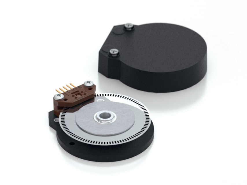
The E3 optical rotary encoder contains a precision machined aluminum hub with a specially patterned Mylar disk. This disk, in combination with our proprietary optical encoder module, creates a system that is highly tolerant to mechanical misalignment.
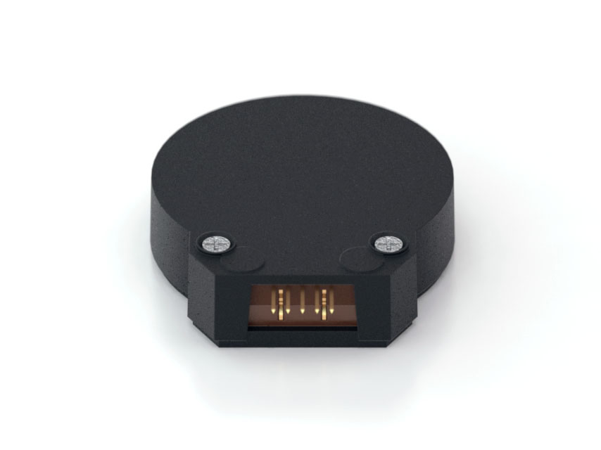
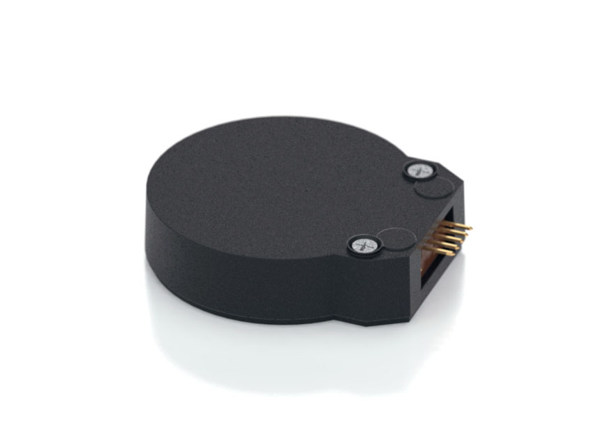
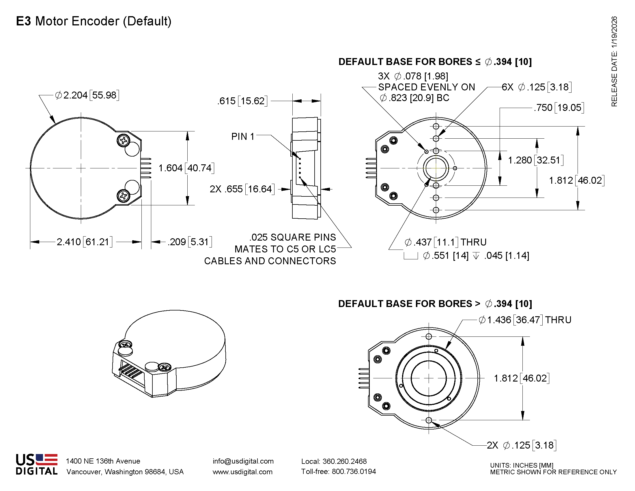
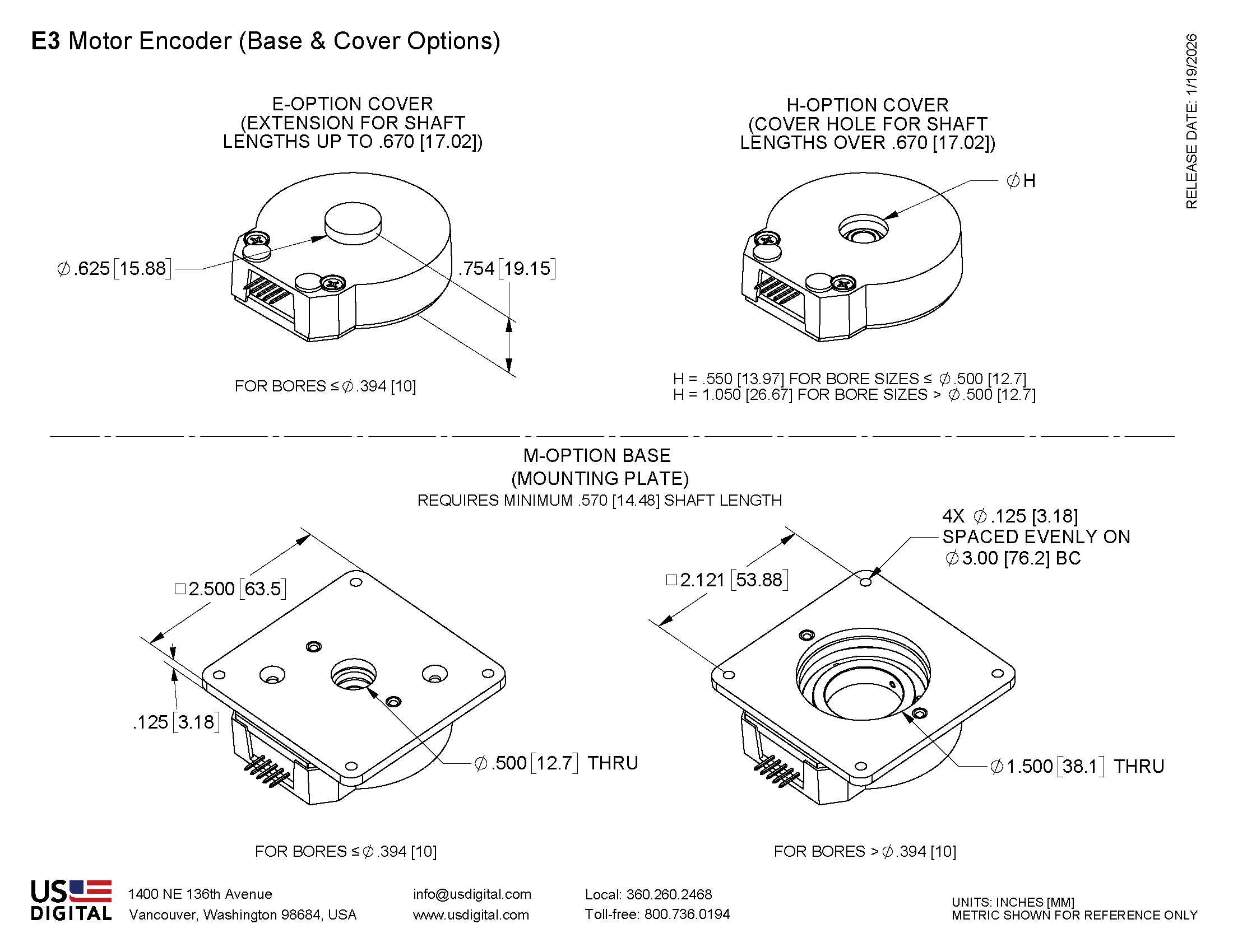
The E3 is available with two base configurations and three cover styles, which allow it to fit a wide range of applications. The output for this optical rotary encoder is single-ended. If your application requires a differential output (due to needing a cable over 10 feet or is located in an electrically noisy environment) you can either add a PC4 / PC5 differential line driver or check out our E6
This incremental encoder is designed for use with a high-retention connector. After making each selection in the Product Configurator, compatible cables and connectors will be displayed below and must be purchased separately.
Additional Information
Product Notes
Cables and connectors are not included and must be ordered separately.
US Digital® warrants its products against defects in materials and workmanship for two years. See complete warranty for details.
Datasheet
Feedback
US Digital's mission is a commitment to quality and constant improvement. If you find an error to a product on this page, please let us know !
Save Your Configuration
Easily keep track of your custom part numbers
What is this feature?
While configuring your encoder, you can save your custom part number at any stage. This helps you keep track of multiple configurations without needing to start over or write anything down.
How does it work?
Click “Add This Configuration to Your List” after selecting your options.
Your saved part number will appear in a mini list below the configurator.
The list is stored locally in your browser and persists across product pages.
Enter a quantity to view default pricing.
What can you do with saved configurations?
When you're ready, visit the Saved Configurations List page to:
Review all saved part numbers
Fill out a form to send your selections to US Digital Customer Service
Receive follow-up to complete your order or get support
Why use it?
Save time by avoiding repeated configurations
Compare multiple part numbers side-by-side
Simplify communication with our support team
Got it!