E4 Product Description
THE E4 ENCODER HAS BEEN DISCONTINUED AND IS REPLACED BY THE E4T .
The E4 miniature encoder is designed to provide digital quadrature encoder feedback for applications with limited space constraints. The E4 utilizes a traditional set-screw encoder disk which accommodates shaft sizes from 1.5mm to 4mm in diameter.
For high quantity OEM applications, US Digital offers a cost-saving OEM packaging option. When a set screw is not required, the E4P is the ideal choice for high-quality OEM applications (see the E4P page).
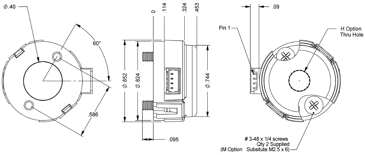
The E4 base provides mounting holes for two #3-48, length 1/4 in. or two M2.5x.45mm, length 6mm screws on a .586 in. bolt circle. When mounting holes are not available, a pre-applied transfer adhesive (with peel-off backing) is available for "stick-on" mounting.
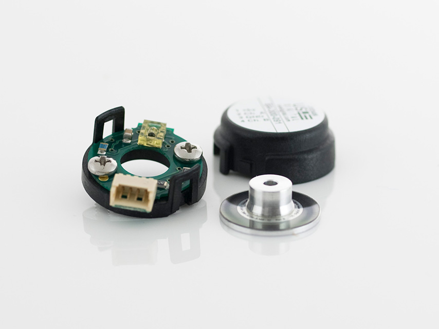
The internal components consist of a precision machined aluminum hub and an encoder circuit board module.
The encoder cover is easily snapped onto the base and is embossed with the connector pin-out.
The E4 series encoder can be connected using a (high retention 4-conductor snap-in polarized 1.25mm pitch) connector. Mating cables and connectors (see the Cables /Connectors page) are not included and are available separately.
Product Specifications
ENVIRONMENTAL
PARAMETER
MIN.
MAX.
UNITS
Vibration (5Hz to 2kHz)
-
20
G
Relative Humidity
-
90
%
Storage Temperature
-40
100
C
Operating Temperature
-20
100
C
ESD (Human Body Model JESD22-A114-A
-
3
kV
ESD (Machine Model JESD22-A115-A
-
300
V
MECHANICAL
PARAMETER
VALUE
UNITS
Moment of Inertia
7.4 x 10^-6
oz-in-s²
Hub Set Screw Size
#3-48 or #4-48
in.
Hex Wrench Size
.050
in.
Hub Setscrew Torque
1.5-2.0
in.-lbs.
Mounting Screw Size
#3-48 x 1/4"
-
M-option Screw Size
M2.5x.45mm, length 6mm
-
Screw Bolt Circle Diameter
.586 ± .002
in.
Base Mounting Screw Torque
2-3
in.-lbs.
Required Shaft Length (1)
.285 to .395
in.
Shaft Axial Play
± .020
in.
Off-axis Mounting Tolerance
± .010
in.
Shaft to Mounting Surface Perpendicularity
90 ± 1
deg.
Acceleration
250000 max.
rad/sec²
Technical Bulletin TB1001 - Shaft and Bore Tolerances
Download
(1) Includes axial play.
ELECTRICAL
PARAMETER
MIN.
TYP.
MAX.
UNITS
NOTES
Power Supply Voltage
4.5
5.0
5.5
V
Power Supply Current
-
21
27
mA
no load on outputs
High Level Output Voltage
2.4
-
-
V
IOH = -1.2 mA
Low Level Output Voltage
-
-
0.4
V
IOL = 6.0 mA
Rise Time
-
500
-
ns
CL = 25pF, RL = 2.7kOhm
Fall Time
-
100
-
ns
PHASE RELATIONSHIP
PARAMETER
TYP.
UNITS
Symmetry, S
180 ± 16
electrical degrees
Quadrature Delay, Q
90 ± 12
electrical degrees
A leads B for clockwise shaft rotation, B leads A for counter clockwise shaft rotation viewed from the cover/label side of the encoder.
PIN-OUT
PIN
DESCRIPTION
1
+5VDC power
2
A channel
3
Ground
4
B channel
OPTIONS
H-OPTION (HOLE IN COVER)
The H -option adds a hole in the cover for the shaft to pass through:
For shaft diameters of 1.5mm to 1/8", a 0.170" hole is supplied.
For shaft diameters of 5/32" and 4mm, a 0.295" hole is supplied.
L-OPTION (LOW POWER STROBE)
L -option To reduce the average power requirements, the L-option version of the E4P power can be strobed on just long enough to sample outputs A and B. This option is the same as our standard E4P , except the internal power bypass capacitor is not installed. The outputs settling time is typically 200 to 400 nano seconds after power up. The minimum sample frequency must be less than the maximum RPM X the CPR / 10.
M-OPTION (METRIC MOUNTING SCREWS)
Provides alternate metric M2.5x.45mm, length 6mm screws. When M -option is NOT specified the default is #3-48 x 1/4" screws.
T-OPTION (TRANSFER ADHESIVE)
When mounting holes are not available, a pre-applied transfer adhesive (with peel-off backing) is available for "stick-on" mounting. Use the centering tool (above) to position the base. T -option specifies transfer adhesive.
ACCESSORIES
CENTERING TOOLS
Part #: MCTOOL - (Shaft Diameter*)
Description: This reusable tool provides a simple method for accurately centering the E4 base onto the shaft.
Material: Aluminum.
Please note: A centering tool is highly recommended when using the T -option transfer adhesive.
* See Ordering Information below for available Shaft Diameters.
SPACER TOOL
Part #: SPACER-4216
Description: This reusable tool is used to properly space the codewheel from the encoder base. Nylon. Round. Provides air gap of 0.07" to 0.03".
HEX TOOLS
Part #: HEXD-050
Description: Hex driver, .050" flat-to-flat for 3-48 or 4-48 set screws.
Part #: HEXW-050
Description: Hex wrench, .050" flat-to-flat for 3-48 or 4-48 set screws.
ASSEMBLY INSTRUCTIONS
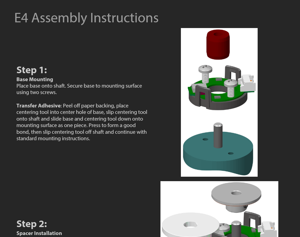
1. Base Mounting
Place base onto shaft. Secure base to mounting surface using two screws.
Transfer Adhesive: Peel off paper backing, place centering tool into center hole of base, slip centering tool onto shaft and slide base and centering tool down onto mounting surface as one piece. Press to form a good bond, then slip centering tool off shaft and continue with standard mounting instructions.
2. Spacer Installation
Place spacer tool on optic module as shown below.
3. Codewheel Installation
Slip codewheel onto shaft until it bottoms out against spacer tool. Spacer tool provides an air gap of 0.07" 0.03". Tighten set screw with either the hex wrench / hex driver while pressing down on codewheel.
4. Cover Installation
Place housing (cover) on. With thumb and finger, squeeze ears together to insure that cover fully latches.
PRODUCT CHANGE NOTIFICATIONS
Title
Date
Description
Download
E4, E4P, S4 - PCN 5741
05/09/2016
As part of our on-going product lifecycle management process, we have identified products that will be transitioned to an "End-of-Life" status. Products targeted for end-of-life may be available for a last time buy option prior to being made obsolete, however quantities are limited, and special requirements may apply.
Download
E4 - E4P - S4 Update - PCN 1014
11/29/2011
We have modified the E4, E4P and S4 product lines in order to improve the performance and durability of the encoder. Changes include new molds for the plastic base and cover parts with an over-molded bushing in the S4 base, a new SMT connector (compatible with current mating connector), and a modified PCB profile to accommodate the new connector and plastic part modifications.
Download
Additional Information
Product Notes
Cables and connectors are not included and must be ordered separately.
US Digital® warrants its products against defects in materials and workmanship for two years. See complete warranty for details.
Related
Datasheet
Feedback
US Digital's mission is a commitment to quality and constant improvement. If you find an error to a product on this page, please let us know !
Save Your Configuration
Easily keep track of your custom part numbers
What is this feature?
While configuring your encoder, you can save your custom part number at any stage. This helps you keep track of multiple configurations without needing to start over or write anything down.
How does it work?
Click “Add This Configuration to Your List” after selecting your options.
Your saved part number will appear in a mini list below the configurator.
The list is stored locally in your browser and persists across product pages.
Enter a quantity to view default pricing.
What can you do with saved configurations?
When you're ready, visit the Saved Configurations List page to:
Review all saved part numbers
Fill out a form to send your selections to US Digital Customer Service
Receive follow-up to complete your order or get support
Why use it?
Save time by avoiding repeated configurations
Compare multiple part numbers side-by-side
Simplify communication with our support team
Got it!