ESWITCH ENCODER SPEED/POSITION SENSING SWITCH

ESWITCH Features

  • Wide 6-25V supply range
  • Covers most useful RPM ranges with 256 CPR encoder
  • Simple DIP switch programming
  • Isolated relay output

See more info below

Configure the ESWITCH

The ESWITCH is no longer available for purchase.

ESWITCH Product Description

The ESWITCH is an encoder speed/position sensing device with an isolated SPDT relay output. This product uses incremental encoder feedback to serve as a speed switch or as a position switch. The relay will be activated for 1 second when the speed threshold is exceeded or if the position deviates from the present position by a programmable threshold. Two encoder connectors are provided in parallel to make it convenient to loop the encoder signals through the ESWITCH. A series of 12 DIP switches program the ESWITCH. DIP switch 12 is not used.

Product Specifications

View here or download the specifications

ELECTRICAL

PARAMETER MIN. TYP. MAX. UNITS NOTES
Supply Voltage 6   25 V  
Supply Current   110   mA 12V power, no encoders
Voltage Out to Encoder 4.8 5.0  5.2  @100mA load 
Encoder Current     250  mA  5V power out for encoder 
Quadrature Input Frequency     400  kHz   
Quadrature Encoder Inputs - Logic Low  0.4 0.8  Diode clamped to ground,
5k pullup to 5V 
Quadrature Encoder Inputs -Logic High 2.0  5.0  5.75  Diode clamped to ground,
5k pullup to 5V 
Relay Contact Rating     2.0  External "catch" diode should be used for inductive loads 
Relay Dielectric Strength 500
500 
    VAC
VAC 
Open contacts
Contacts to Coil  
Relay Contact Resistance     100 uohms   
  • The ESWITCH is normally powered through the power connector, but it may also be powered via J1, pin 5.

SPEED SENSING MODE

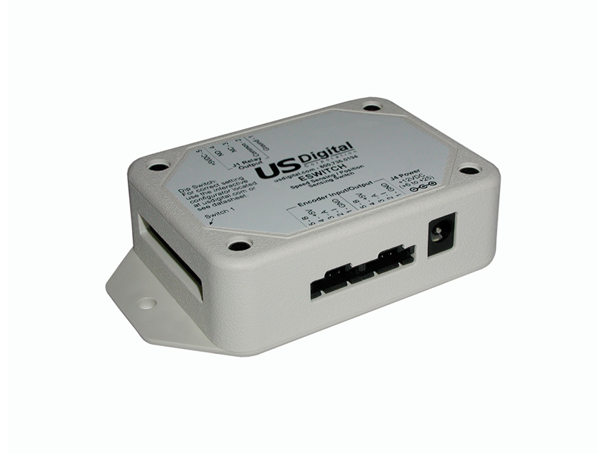
DIP Switch SW11 = "up" for this mode.

In speed sensing mode, the relay will activate for approximately 1 second when the sensed RPM is equal to or greater than the RPM threshold. DIP Switches SW1 to SW10 are used to set the threshold value. The output relay has both normally open and normally closed contacts available to the user.

The CPR of the encoder must be chosen according to the desired RPM range: 


ENCODER CPR RPM RANGE
200 28 to 7004
256 21 to 5470
512 11 to 2736
1024 6 to 1268


DIP switch SW10,SW9,SW8 setting:

Calculate the PRESET value from the desired RPM threshold, RPMT and the encoder CPR using the formula:

PRESET = 1920 / (RPMT * CPR)

Look up the SW10/SW9/SW8 setting based on the PRESET value using the table below and note the corresponding PREOUT constant value. If PRESET is outside the range of the table, lower the encoder CPR to get the value within range.


PRESET RANGE SW10 SW9 SW8  PREOUT
0.1747601 to 0.3495300  0.3495300
0.0873811 to 0.1747600  0.1747600
0.0436911 to 0.0873810  0.0873810
0.0218451 to 0.0436910  0.0436910
0.0109231 to 0.0218450  0.0218450
0.0054614 to 0.0109230  0.0109230
0.0027308 to 0.0054613  0.0054613
0.0000000 to 0.0027307  0.0027307


 DIP Switch SW7 to SW1 setting:

Calculate the offset value as shown below:

OFFSETV = ( (RPMT * CPR * PREOUT) / 15 ) - 128

Convert the OFFSETV to binary and enter the value on SW7 to SW1.  SW7 is the most significant bit. DIP Switch down = 0 and DIP Switch up = 1

POSITION SENSING MODE

DIP Switch SW11 = "down" for this mode.

In this mode, an internal up / down counter will decode quadrature states and track the position of the external encoder. DIP switches SW1 through SW7 allow the user to set the number of counts from 1 to 127 in binary. SW7 is the most significant bit. DIP Switch down = 0 and DIP Switch up = 1. The relay will be activated for about 1 second when the counter deviates from the current position by the programmed count value. The counter will auto-reset to zero whenever the trigger point is reached. The output relay has both normally open and normally closed contacts available to the user.

Example:
If the DIP switches are set to 12 in binary, then the relay output will be activated for 1 second when the shaft rotates 12 quadrature states in either direction.  The shaft will need to deviate from the current position by 12 quadrature states to activate again.

PIN-OUTS

Encoder Input/Output

PIN DESCRIPTION
1 Ground
2 Index
3 A channel
4 +5V power
5 B channel


J1 Connector

PIN DESCRIPTION
1 Ground
2 Relay Common Contact
3 Relay N.C. contact
4 Relay N.O. contacy
5 Input Supply Voltage

PRODUCT CHANGE NOTIFICATIONS

Title Date Description Download
PCN 1011 9/21/2011 The AD2B, AD4B, AD7, EADAPT, EDAC2, EDIVIDE, EPOT, EQUAD, ESUM, ESWITCH, ETACH2, SEI-USB, USB-232 currently utilizes a printed thermal transfer label. This label will no longer be used and will be replaced by laser marking directly onto the housing of the product. The purpose for this change is to create a more durable solution and eliminate the possibility of the label being inadvertently removed from the housing. Download

Additional Information

Product Notes

  • Cables and connectors are not included and must be ordered separately.
  • US Digital® warrants its products against defects in materials and workmanship for two years. See complete warranty for details.

Datasheets


Feedback

US Digital's mission is a commitment to quality and constant improvement. If you find an error to a product on this page, please let us know!