
A2K Absolute Encoder Kit
A2K Features
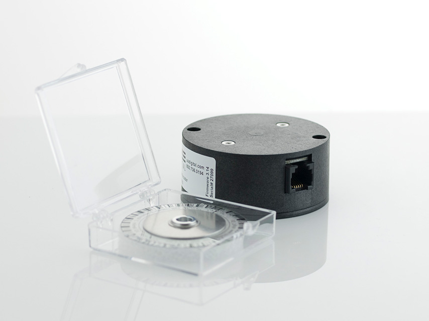
- Installs onto shafts up to 10mm diameter
- 12-bit resolution, and resolution field programmable from 2 to 4,096 codes per revolution (3,600 factory default)
- Full 360 degrees range, 7 msec update time
- Low power drain of 18.5 mA max., and 2.5 mA in sleep mode
- Field programmable parameters such as setting zero position point (free demo software provided)
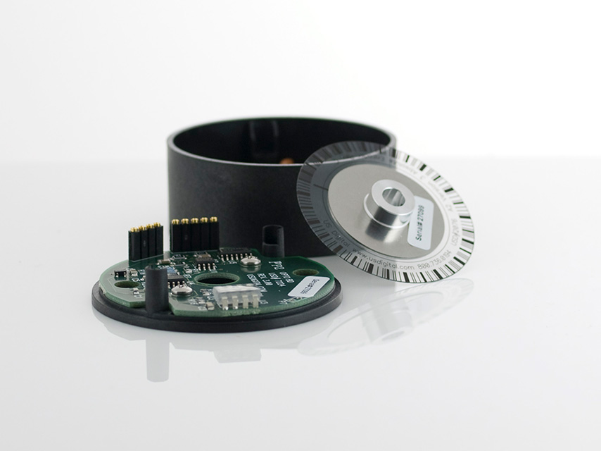
- EEPROM stores downloadable parameters
- 9,600 baud default data rate adjustable up to 115K baud
- 12-bit analog voltage output option (0 to +3.599 volts factory default setting. Field programmable up to 0 to +4.095 volts)
- Multi-turn mode (note: power must be maintained to prevent reset to zero)
- -25 to 70 degrees C. operating temperature
See more info below
Configure the A2K