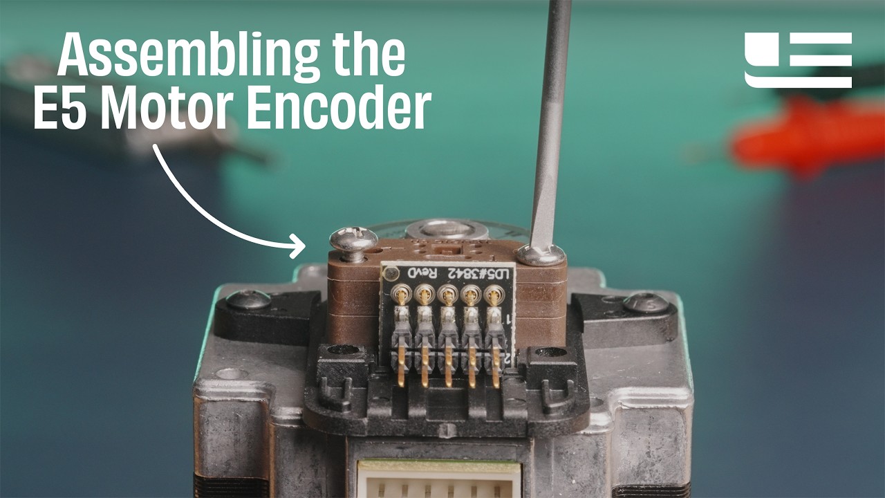
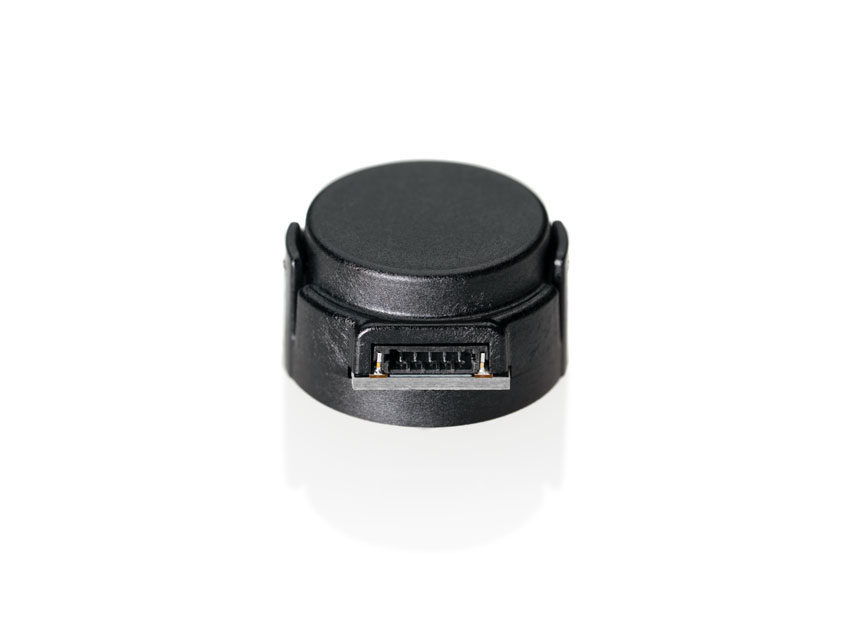
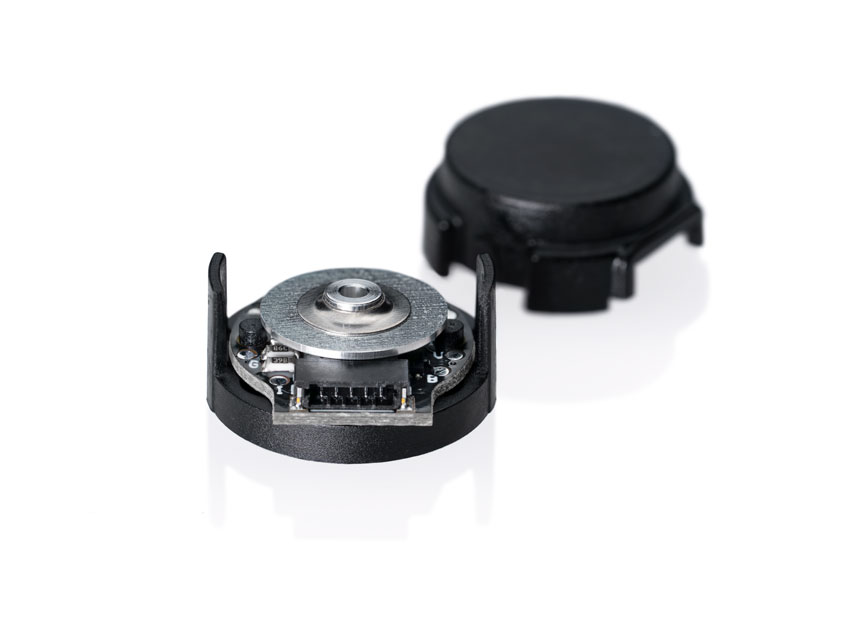
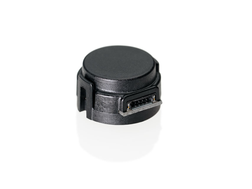
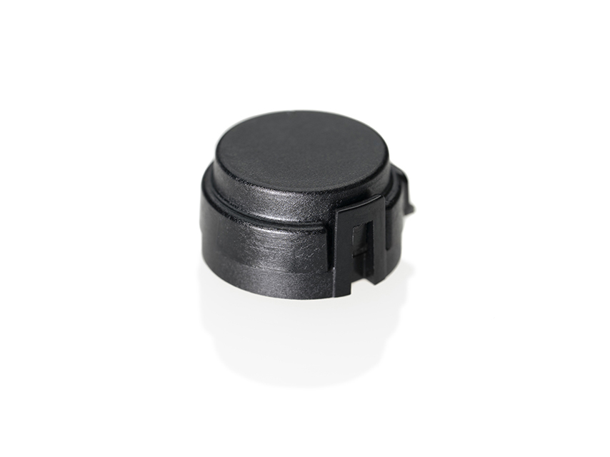
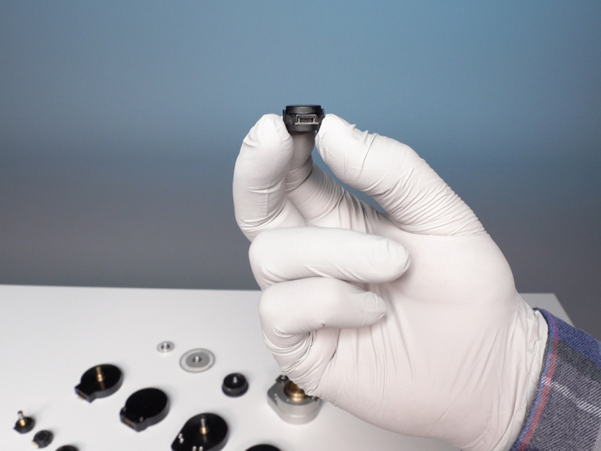
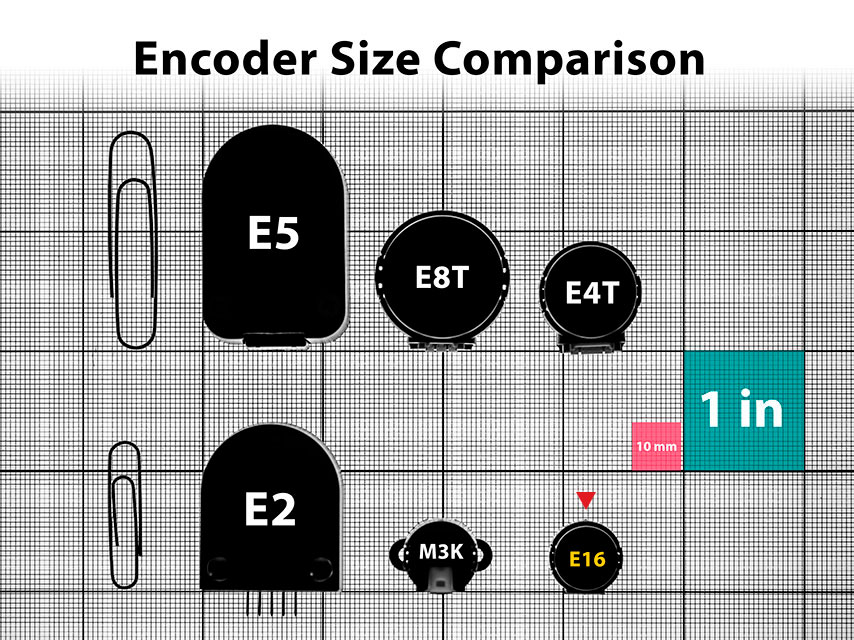
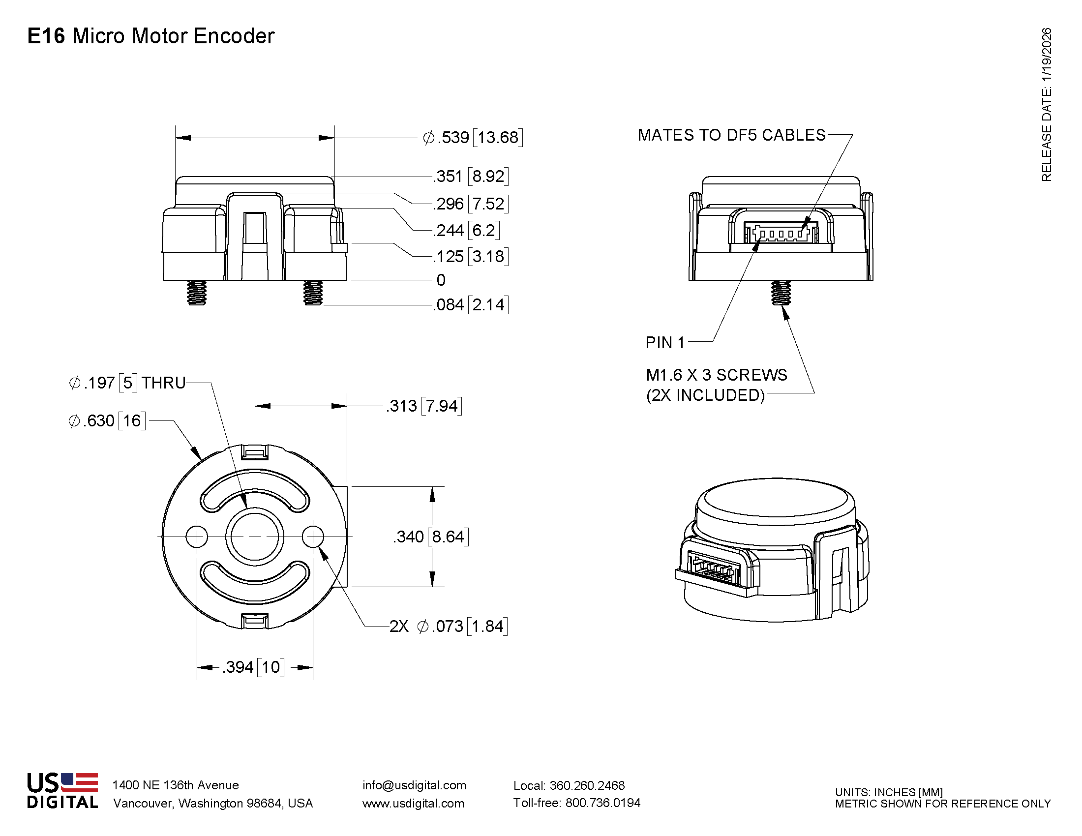
US Digital E16 Motor Encoder Description The E16 micro motor encoder is only 16 mm in diameter and mounts directly to a motor or other rotating shaft. This incremental encoder uses a specially patterned optical disk on a precision-machined aluminum hub.
This disk, in combination with a custom detector, creates a system highly tolerant to mechanical misalignment. A push-on hub design and a robust, glass-filled polymer housing provide easy installation in space-limited applications.
The E16 optical rotary encoder offers 10 resolutions and compatibility with two shaft sizes (1.5 mm and 2.0 mm). It comes standard with a two-channel quadrature output with index.
This optical rotary encoder is designed for use with a polarized connector. After making each selection in the Product Configurator, compatible cables will be displayed below and must be purchased separately.
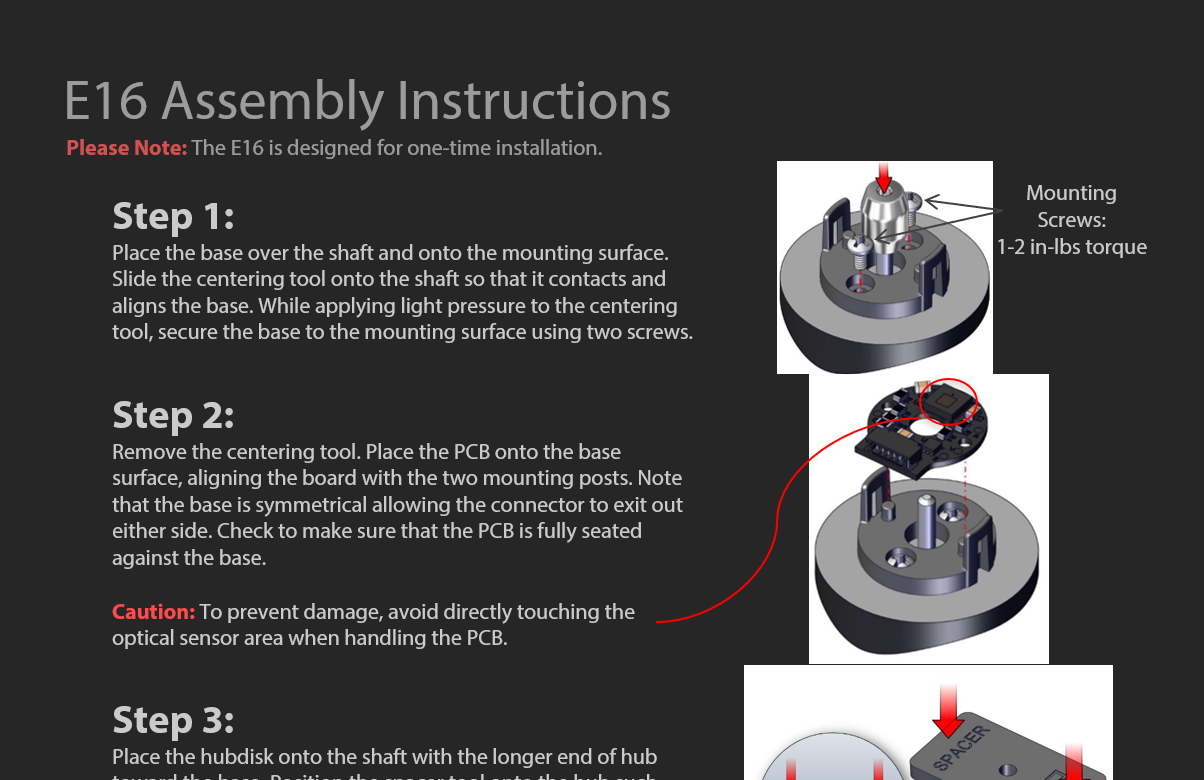
Please Note : Due to the E16's design, it is recommended for use as a one-time installation.
Product Specifications
ENVIRONMENTAL
PARAMETER
VALUE
UNITS
Operating Temperature
-40 to 100
C
Electrostatic Discharge, IEC 61000-4-2
±12
kV
Vibration (10Hz to 2kHz, sinusoidal)
20
G
Shock (6 milliseconds, half-sine
75
G
MECHANICAL
PARAMETER
VALUE
UNITS
Max. Shaft Axial Play
±0.010
in.
Max. Shaft Runout
0.002 T.I.R.
in.
Max. Acceleration
250000
rad/sec²
Maximum RPM, CPR = 250/500/1000/2000
48000
RPM
Maximum RPM, CPR = 256/512/1024/2048
46875
RPM
Maximum RPM, CPR = 4000
27750
RPM
Maximum RPM, CPR = 4096
27099
RPM
Codewheel Moment of Inertia
2.8 x 10⁻⁷
oz-in-s²
Mounting Screw Size
mm
Screw Bolt Circle Diameter
10 ±0.13
mm
Minimum Shaft Length (1)
6
mm
Maximum Shaft Length (1)
7.75
mm
Mounting Screw Torque
1-2
in-lbs
Technical Bulletin TB1001 - Shaft and Bore Tolerances
Download
(1) Including axial play.
ELECTRICAL
PARAMETER
MIN.
TYP.
MAX.
UNITS
NOTES
Supply Voltage
4.5
5.0
5.5
V
Supply Current
18
26
mA
no load
Low-level Output
0.4
V
IOL = 4 mA, Vcc = 5V
High-level Output
4.7
V
IOH = 4 mA, Vcc = 5V
Output Rise Time
80
135
ns
no load
Output Fall Time
80
135
ns
no load
Maximum Output Frequency
PHASE RELATIONSHIP
Specifications apply over the entire operating temperature range.
Values are for the worst error over full rotation.
Refer to the timing diagram below.
PARAMETER
SYMBOL
MIN.
TYP.
MAX.
UNITS
Symmetry
X, Y
150
180
210
°e
Quadrature
Z
60
90
120
°e
Index Pulse Width
Po
60
90
120
°e
Ch. I Rise After Ch. B or Ch. A Fall
t1
10
ns
Ch. I Fall After Ch. B or Ch. A Rise
t2
10
ns
TIMING DIAGRAM
A leads B for clockwise shaft rotation, B leads A for counter clockwise shaft rotation viewed from the cover side of the encoder.
PIN-OUT
PIN
DESCRIPTION
1
Ground
2
Index
3
A channel
4
+5VDC power
5
B channel
ACCESSORIES
1. CENTERING TOOL*
Part #: CTOOL-E16-(Shaft Diameter)
Description: This reusable tool is used to accurately center the E16 base on the shaft.
2. SPACER TOOL*
Part #: SPACER-E16
Description: This reusable tool is used to properly space the codewheel from the encoder.
*Both the CTOOL and SPACER-E16 tools are included with all packaging options.
3. SCREWS
Part #: SCREW-M16-3MM-PH
Description: Pan Head, Philips M1.6-0.35, length 3mm.Use: Base MountingQuantity Required: 2
Additional Information
Product Notes
Cables and connectors are not included and must be ordered separately.
US Digital® warrants its products against defects in materials and workmanship for two years. See complete warranty for details.
Assembly Instructions
Press Releases
3D Model Downloads
Please
configure your product first
to download a 3D model. (Note: The formats below will become links if there are 3D models available.)
SolidWorks Format
IGES Format
Parasolid Format
STEP Format
Datasheet
Feedback
US Digital's mission is a commitment to quality and constant improvement. If you find an error to a product on this page, please let us know !
Save Your Configuration
Easily keep track of your custom part numbers
What is this feature?
While configuring your encoder, you can save your custom part number at any stage. This helps you keep track of multiple configurations without needing to start over or write anything down.
How does it work?
Click “Add This Configuration to Your List” after selecting your options.
Your saved part number will appear in a mini list below the configurator.
The list is stored locally in your browser and persists across product pages.
Enter a quantity to view default pricing.
What can you do with saved configurations?
When you're ready, visit the Saved Configurations List page to:
Review all saved part numbers
Fill out a form to send your selections to US Digital Customer Service
Receive follow-up to complete your order or get support
Why use it?
Save time by avoiding repeated configurations
Compare multiple part numbers side-by-side
Simplify communication with our support team
Got it!