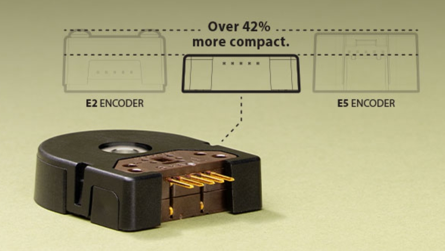
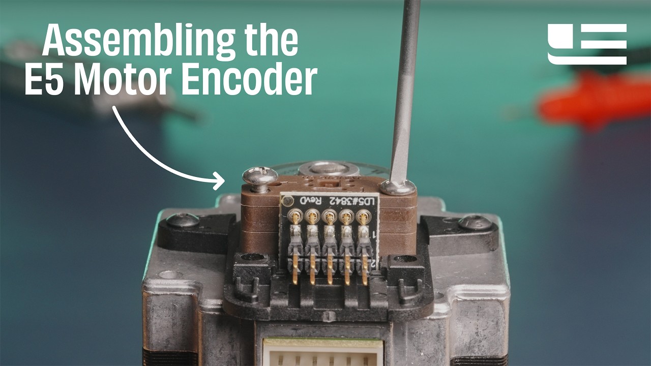
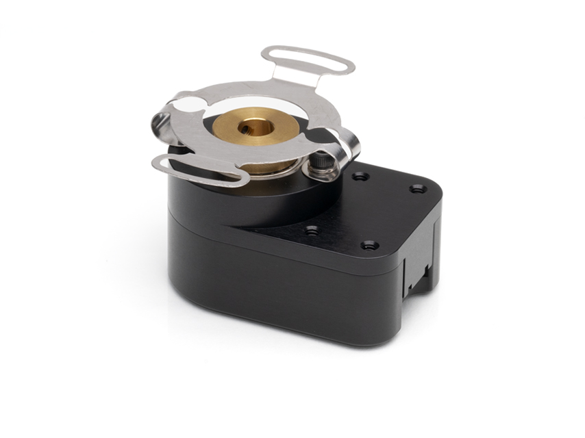
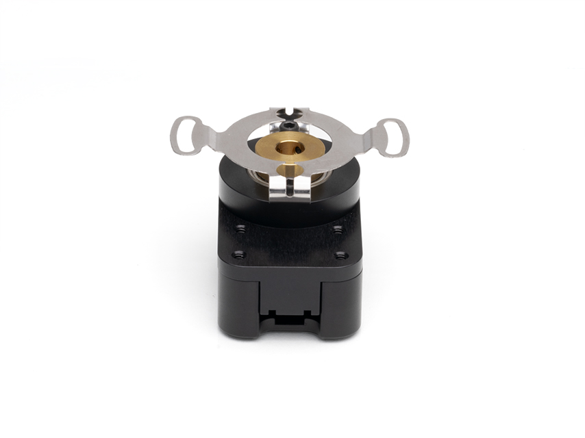
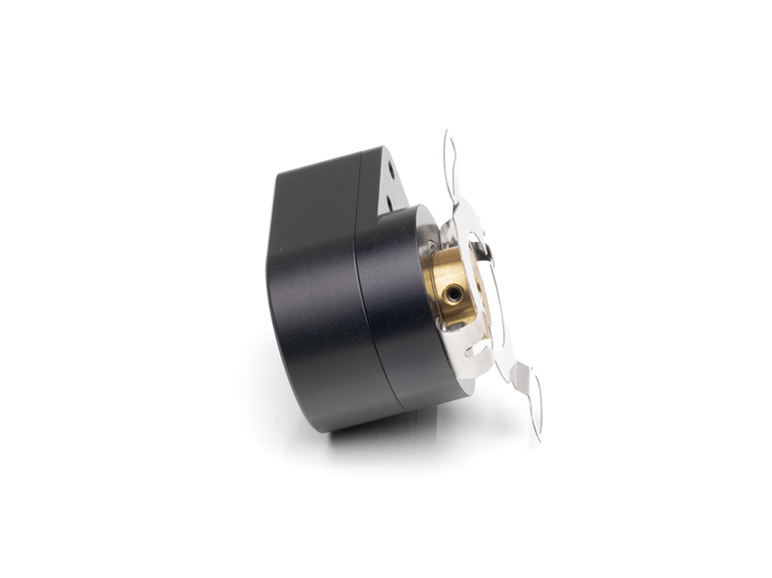
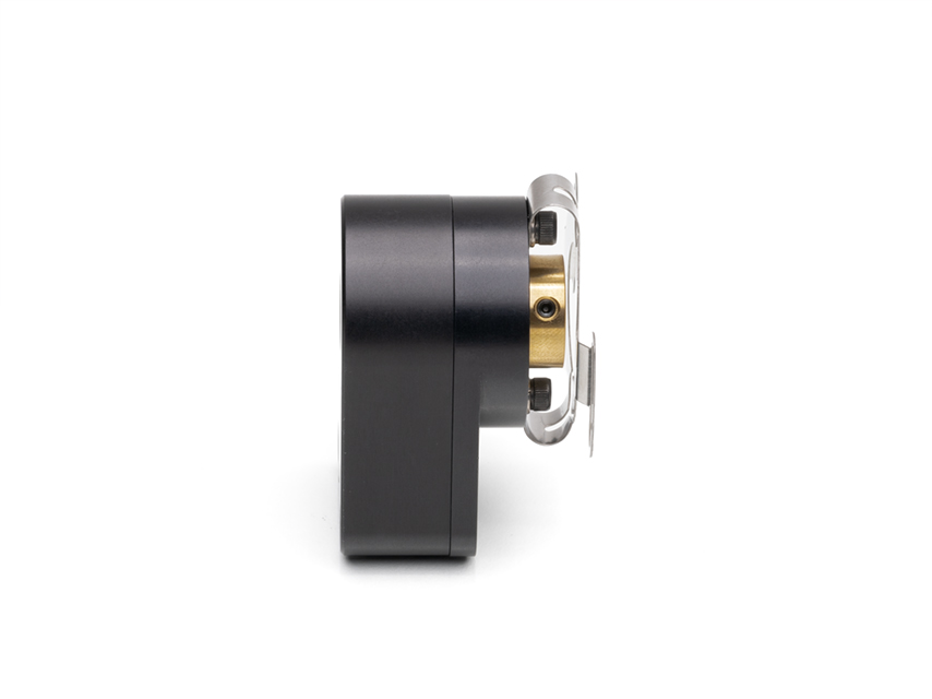
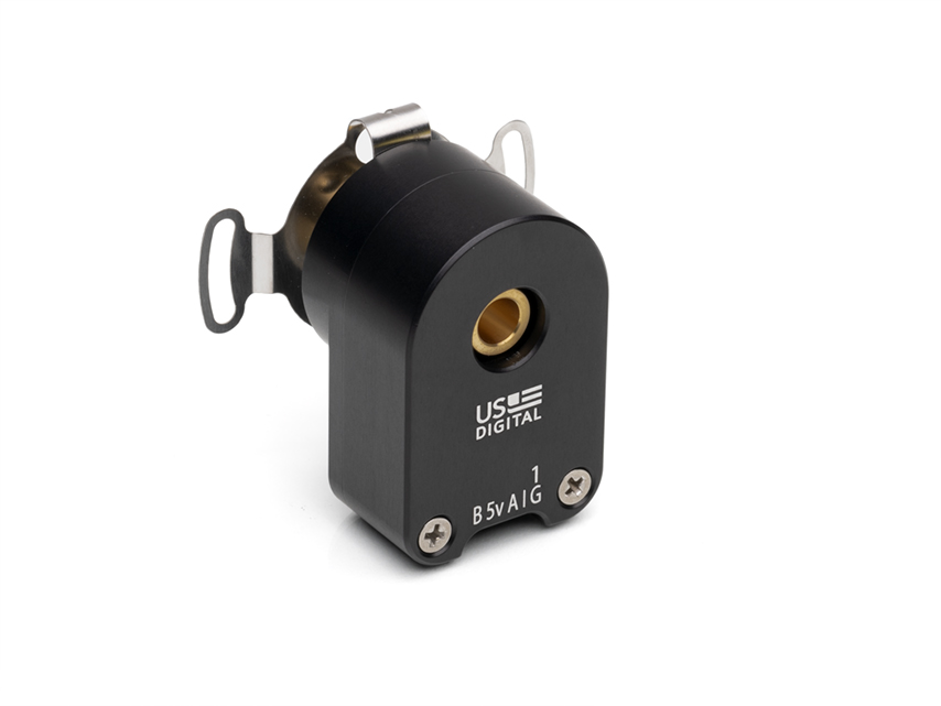
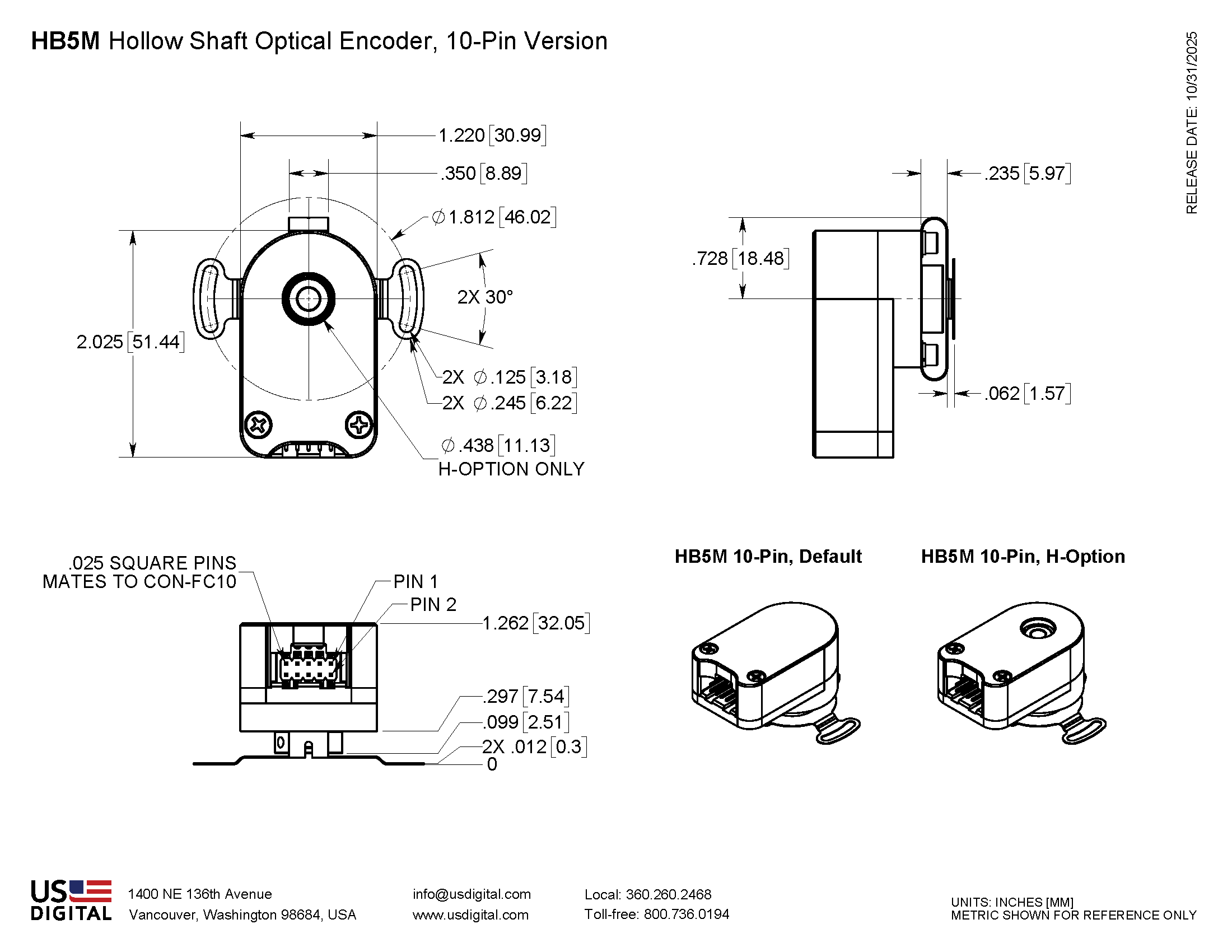
HB5M Product Description
The HB5M is a hollow bore (hollow shaft/thru-bore) optical encoder with a machined aluminum enclosure and an anodized protective finish. The HB5M optical incremental encoder is designed to easily mount to an existing shaft to provide digital feedback information. Typical applications include motor feedback, process control, robotics, textile machines, and elevator controls.
The HB5M bearing style encoder features a hollow bore that accepts shaft diameters from 5mm to 8mm in diameter. The encoder slips over the shaft and is locked into place with two 4-48 set screws. A flexible anti-rotation mount makes the encoder more tolerant of shaft runout than a standard kit encoder. The HB5M can accommodate shaft runout up to 0.030 in. axial and 0.010 in. radial. The flexible tether provides mounting for two 4-40 machine screws on a 1.812 in. bolt circle.
The HB5M housing comes standard with a closed cover or an optional hole in the body to allow a shaft to pass completely through the encoder.
The differential version has an internal differential line driver (26C31) that can source and sink 20mA at TTL levels. The cable connected to this encoder should have 3 twisted pairs for the data channels plus power and ground. The recommended receiver is the industry-standard 26C32.
The mating connector is polarized and latches into the encoder. Depressing the latch tab allows the connector to be unplugged. Mating connector assemblies are available from US Digital. Custom cables are also readily available (see the Cables/Connectors page).
Product Specifications
View here or download the specifications
ENVIRONMENTAL
PARAMETER |
VALUE |
UNITS |
Operating Temperature, CPR < 2000 |
-40 to 100 |
C |
Operating Temperature, CPR ≥ 2000 |
-25 to 100 |
C |
Vibration (5Hz to 2kHz) |
20 |
G |
Shock, 11 mSec |
50 |
G |
Electrostatic Discharge Single-ended (-S version), IEC 61000-4-2 Differential (-D version), Human Body Model |
± 4 ± 2 |
kV |
MECHANICAL
Parameter |
Value |
Max. Acceleration |
100000 rad/sec2 |
Max. Shaft Speed (mechanical) |
6000 rpm (1) |
Max. Starting Torque |
0.20 oz-in |
Max. Bore Load |
2 lb. |
Weight |
2.84 oz. |
Max. Shaft Runout |
0.010 in. T.I.R. |
Max. Shaft Axial Play |
± 0.030 in. |
Required Shaft Length (From mounting surface) |
Min. = 0.3 in. Max. = 1.0 in. with default cover. Max. = No limit with H-option cover. |
Moment of Inertia |
1.29 x 10^-4 oz-in-sec2 |
Technical Bulletin TB1001 - Shaft and Bore Tolerances |
Download |
(1) The maximum speed due to electrical considerations is dependent on the CPR. See the EM1 and EM2 product pages.
PHASE RELATIONSHIP
A leads B in a clockwise shaft rotation, and B leads A in counterclockwise shaft rotation when viewed from the rear side (opposite flexible mount) of the encoder.
SINGLE-ENDED ELECTRICAL
- Specifications apply over the entire operating temperature range.
- Typical values are specified at Vcc = 5.0Vdc and 25°C.
- For complete details, see the EM1 or EM2 product pages.
PARAMETER |
MIN. |
TYP. |
MAX. |
UNITS |
CONDITIONS |
Supply Voltage |
4.5 |
5.0 |
5.5 |
V |
|
Supply Current |
|
27 |
33 |
mA |
CPR < 500, no load |
|
54 |
62 |
mA |
CPR ≥ 500 and < 2000, no load |
|
72 |
85 |
mA |
CPR ≥ 2000, no load |
Low-level Output |
|
|
0.5 |
V |
IOL = 8mA max., CPR < 2000 |
|
|
0.5 |
V |
IOL = 5mA max., CPR ≥ 2000 |
|
0.05 |
|
V |
no load, CPR < 2000 |
|
0.25 |
|
V |
no load, CPR ≥ 2000 |
High-level Output |
2.0 |
|
|
V |
IOH = -8mA max. and CPR < 2000 |
2.0 |
|
|
V |
IOH = -5mA max. and CPR ≥ 2000 |
|
4.8 |
|
V |
no load and CPR < 2000 |
|
3.5 |
|
V |
no load and CPR ≥ 2000 |
Output Current Per Channel |
-8 |
|
8 |
mA |
CPR < 2000 |
-5 |
|
5 |
mA |
CPR ≥ 2000 |
Output Rise Time |
|
110 |
|
nS |
CPR < 2000 |
|
50 |
|
nS |
CPR ≥ 2000, ± 5mA load |
Output Fall Time |
|
100 |
|
nS |
CPR < 2000 |
|
50 |
|
nS |
CPR ≥ 2000, ± 5mA load |
DIFFERENTIAL ELECTRICAL
- Specifications apply over the entire operating temperature range.
- Typical values are specified at Vcc = 5.0Vdc and 25°C.
- For complete details, see the EM1 or EM2 product pages.
PARAMETER |
MIN. |
TYP. |
MAX. |
UNITS |
CONDITIONS |
Supply Voltage |
4.5 |
5.0 |
5.5 |
V |
Supply Current |
|
29 |
36 |
mA |
CPR < 500, no load |
|
56 |
65 |
mA |
CPR ≥ 500 and < 2000, no load |
|
74 |
88 |
mA |
CPR ≥ 2000, no load |
Low-level Output |
|
0.2 |
0.4 |
V |
IOL = 20mA max. |
High-level Output |
2.4 |
3.4 |
|
V |
IOH = -20mA max. |
Differential Output Rise/Fall Time |
|
|
15 |
nS |
|
PIN-OUTS
5-PIN SINGLE-ENDED:
PIN |
DESCRIPTION |
1 |
Ground |
2 |
Index |
3 |
A channel |
4 |
+5VDC power |
5 |
B channel |
10-PIN DIFFERENTIAL
PIN |
DESCRIPTION |
1 |
Ground |
2 |
Ground |
3 |
Index- |
4 |
Index+ |
5 |
A- channel |
6 |
A+ channel |
7 |
+5VDC power |
8 |
+5VDC power |
9 |
B- channel |
10 |
B+ channel |
PRODUCT CHANGE NOTIFICATIONS
Title |
Date |
Description |
Download |
EM1 LED Die - PCN 1016 |
2/7/2013 |
As part of US Digital's continual assurance of supply strategy, we have qualified additional sources for our LED die used in our EM1 encoder module, which in turn impacts all of the following products:
EM1, E2, E3, E5, E6, H1, H15, H3, H5, H6, HB5M, HB6M, HD25, PE, S1, S2, S5, S6, T5 and T6
The device specification will remain the same, i.e. there will be no change to form, fit or function of the product(s) as specified by US Digital. The appropriate quality and reliability testing has been performed on representative products to ensure normal parametric distribution, consistent with US Digital's quality and reliability standards. |
Download |
EM1 & EM2 Update - PCN 4199 |
1/14/2014 |
Based on our continuous process improvement program, US Digital is changing the current marking method for our EM1 and EM2 encoder modules to a serialization method. This change will allow for each module to have a unique code; the current marking method is based on a date code system that includes all encoder modules produced within a specific week / year. The serialization system will be based on a hexadecimal system. |
Download |
Additional Information
Product Notes
-
Cables and connectors are not included and must be ordered separately.
-
US Digital® warrants its products against defects in materials and workmanship for two years. See complete warranty for details.
-
For ordering information please see the Compatible Cables / Connectors section above.
Datasheets
Assembly Instructions
Related
3D Model Downloads
Please
configure your product first
to download a 3D model.
(Note: The formats below will become links if there are 3D models available.)
-
SolidWorks Format
-
IGES Format
-
Parasolid Format
-
STEP Format
Product Configurator
Our products are not currently available for direct online purchase. To place an order please contact us directly with your part number.
For purchasing or volume discounts, please configure the part above, then use the completed part number and contact us!
Feedback
US Digital's mission is a commitment to quality and constant improvement. If you find an error to a product on this page, please let us know!