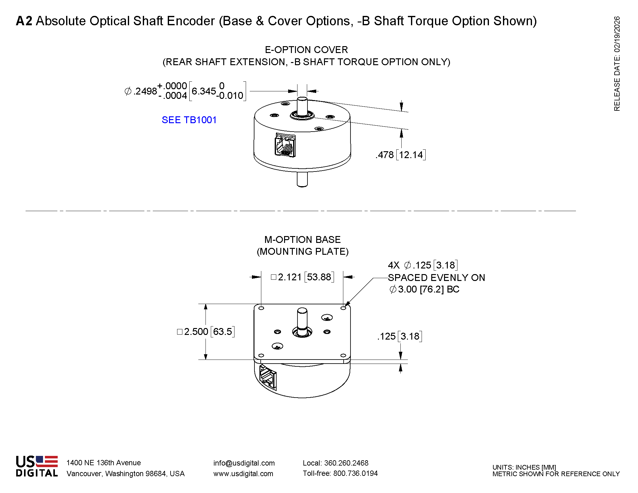
A2 Product Description
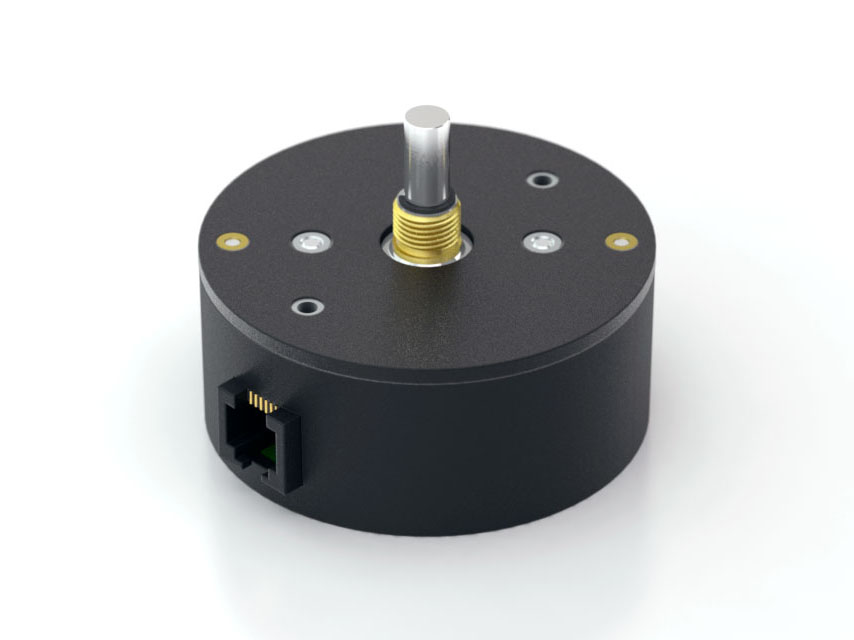
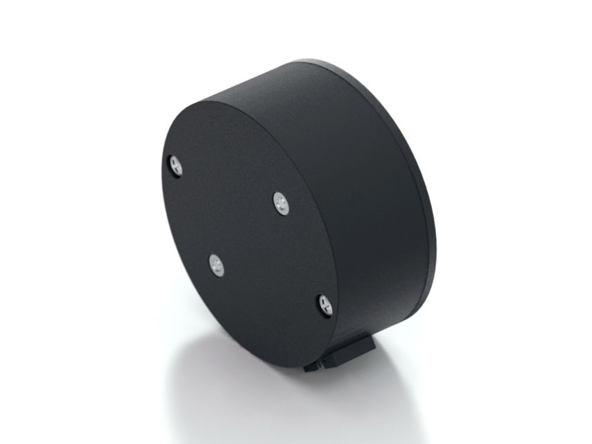
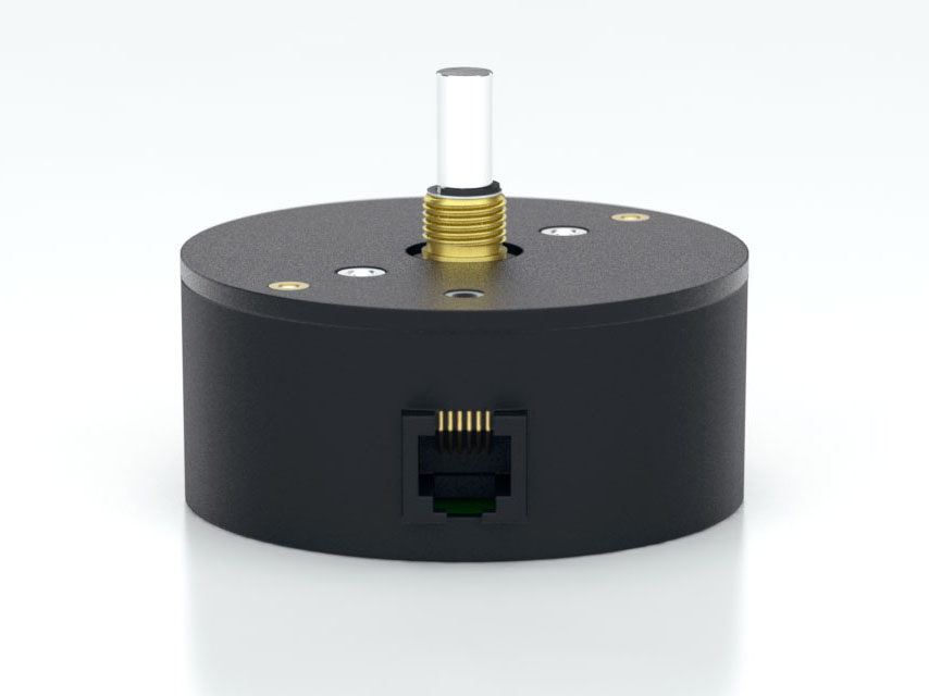
The A2 optical encoder is a 12-bit absolute rotary encoder which reports a shaft angle within a single 360-degree rotation of a shaft. Unlike incremental, sometimes called relative, style encoders, the A2 provides true (absolute) shaft position eliminating the need for a home or zero cycle after a supply voltage power cycle.
Three shaft torque options are available:
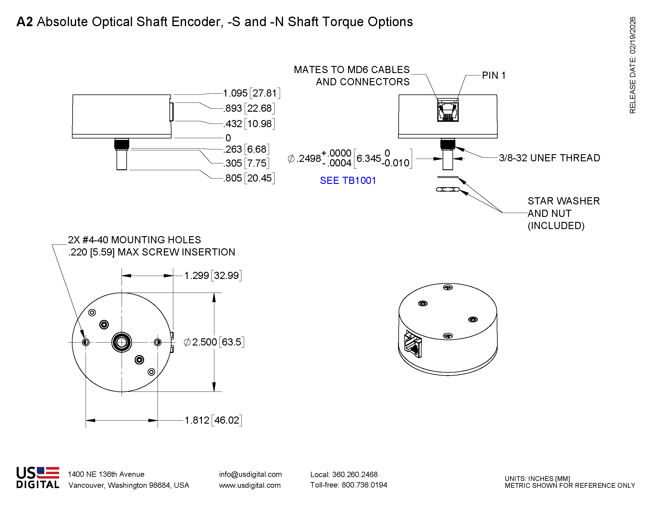
Default (-S): sleeve bushing with higher damping for human interface applications.
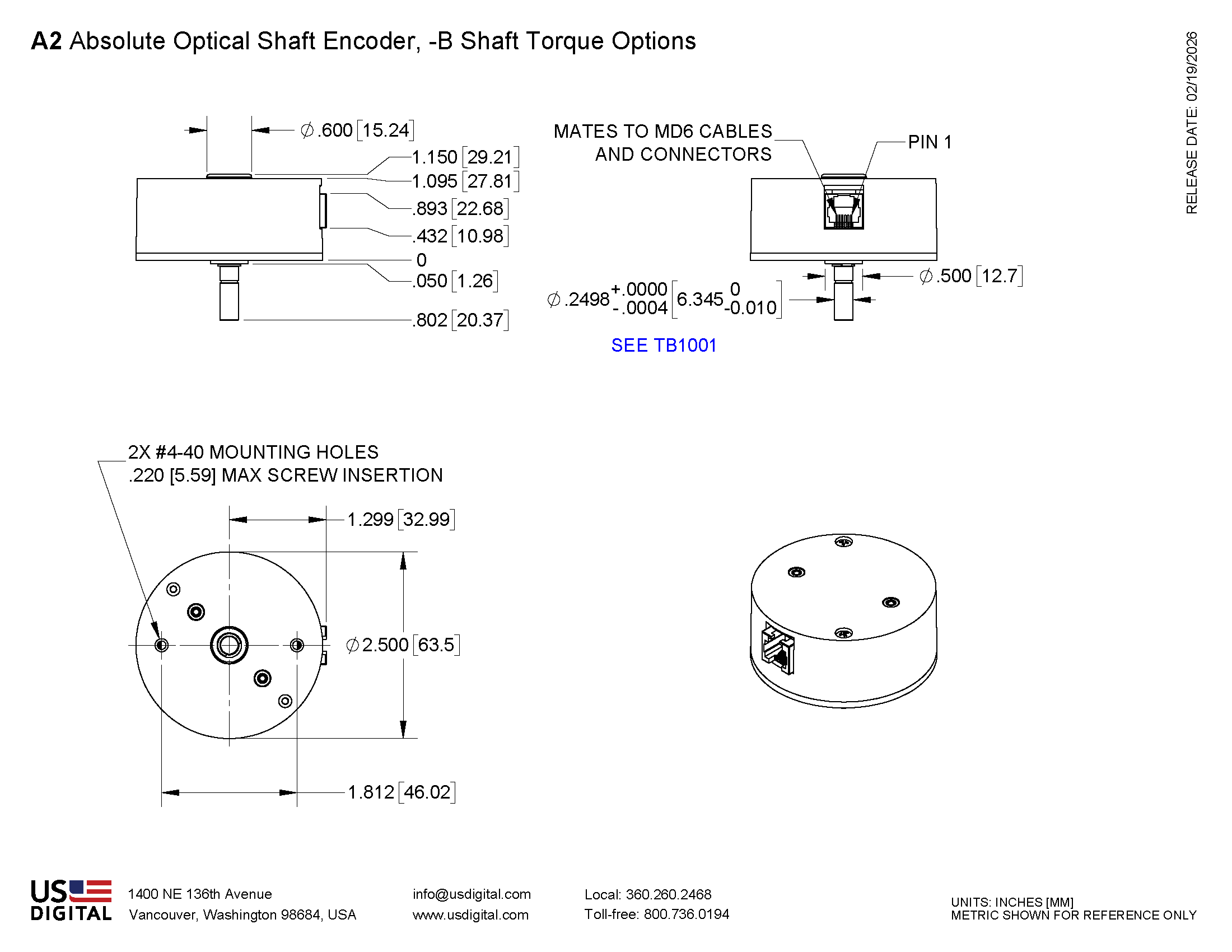
Ball bearing (-B): miniature precision ball bearings suitable for high-speed applications.
Light static drag (-N): sleeve bushing with lower damping for low-speed applications.
The A2 communicates over a RS 485 style serial bus utilizing US Digital's SEI (Serial Encoder Interface), which allows for simple, quick and convenient networking of multiple SEI devices on a single network. PLCs, motion controllers, and computers can also reside on the SEI bus by using US Digital's SEI to USB interface device. For complete information about the SEI bus, please refer to the SEI Absolute Encoder Communications Protocol webpage.
The A2 is also available with an optional analog output. The analog output option provides a maximum voltage range of 0 to 4.095 volts with 12-bit resolution. The output voltage can be scaled by simple SEI commands to provide user-defined voltage ranges. From the factory, the analog output voltage is set to 0 to 3.599 VDC range. Please note that with the A2 analog output option, only one device may reside on an SEI bus.
Product Specifications
ENVIRONMENTAL
PARAMETER
VALUE
UNITS
Operating Temperature
-25 to 70
C
Vibration (5Hz to 2kHz)
20
G
Electrostatic Discharge, IEC 61000-4-2
± 4
kV
MECHANICAL
PARAMETER
SLEEVE BUSHING
BALL BEARING
Max. Acceleration
100000 rad/sec²
100000 rad/sec²
Max. Shaft Speed
100 RPM
10000 RPM
Typical Shaft Torque
0.5 in-oz (S-option)
0.05 in-oz (B-option)
Max. Shaft Loading
2 lb. dynamic
2 lb.
Bearing Life
> 1000000 revolutions
L10 = (90/Fr )³ *L10 = bearing life in millions of revs, andFr = radial shaft loading in pounds
Weight
2.9 oz.
2.9 oz.
Max. Shaft Runout
0.0015 in, T.I.R.
0.0015 in, T.I.R.
Mounting Plate Screw Torque
4-6 in-lbs
4-6 in-lbs
Max. Panel Nut Tightening Torque
20 in-lbs
n/a
Technical Bulletin TB1001 - Shaft and Bore Tolerances
Download
* only valid with negligible axial shaft loading.
ELECTRICAL
Specifications apply over entire operating temperature range.
Typical values are specified at Vcc = 12V and 25C.
Parameter
Min.
Typ.
Max.
Units
Supply Voltage
7.5
12
16
V
Supply Current @ 12V supply
Analog Output Impedance
51
Ohms
Zero Scale Analog Voltage
0
2
12
mV
Full Scale Analog Voltage
4.066
4.095
4.124
V
Output Noise (Analog version)
10
mV rms
Differential Nonlinearity (Analog version)
-1.0
1.0
LSB
Integral Nonlinearity (Analog version)
-1.0
1.0
LSB
Absolute Accuracy (SEI interface version)
0.18
0.25
Degrees
Angle tracking speed
Position Update Rate (1)
7
msec.
(1) The internal microcontroller takes a snapshot of the disk every 7 msec. and stores the position in memory. It responds immediately to a "report position request" by sending the most recently computed position.
DEFAULT SETTINGS
Parameter
Default value
Volatile?
SEI address
0
Non-volatile
Resolution
3600
Non-volatile
Origin offset
0
Non-volatile
Baud rate
9600
Volatile
Mode
0
(1)
(1) Mode is always restored from non-volatile EEPROM on power-up; however, there are separate SEI commands for setting the RAM copy only, or both the RAM copy and the non-volatile EEPROM copy. For an explanation of the Mode bits see SEI Absolute Encoder Communications Protocol .
ANALOG OUTPUT
The analog version of the A2 has a 12-bit DAC on the output which feeds to 2 lines that are otherwise used for the BUSY handshaking pair. This DAC has a full range of 0 to 4.095 Volts which is 1 mV per count. The absolute position value which the internal microcontroller sends to that DAC is the same as the digital value that it sends to the host over SEI. Since the resolution (which represents the number of codes per revolution) is field programmable, the range of the DAC will also follow that setup. The default resolution is 3600 codes per revolution which yields 1 count per a tenth of a degree. This makes the DAC output equal to 1 mV per tenth of a degree or 0 to 3.599 Volts. When the DAC needs to have the full range to 4.095 Volts, the single turn resolution should be set to 4096. This is easily done with the available software which runs on a PC. Cable CA-MD6A-SS-MD6-6FT and the SEI-USB adapter are needed to interface the A2 analog version to a USB port or RS-232 serial COM port.
Please Note: The BUSY handshaking lines are replaced by the analog output option. This means that only one device will be able to be connected to the SEI bus when using the analog output option.
PIN-OUTS
PIN
DESCRIPTION
1
Ground
2
Busy+
3
Busy-
4
Power
5
Data L
6
Data H
PRODUCT CHANGE NOTIFICATIONS
Title
Date
Description
Download
EOL Sealed Housing Option - PCN 1021
4/11/2013
This PCN is a formal notification that US Digital is discontinuing the Sealed Housing option for the following products:
A2 Absolute Optical Encoder
A2T Absolute Optical Inclinometer
H1 Ball Bearing Optical Shaft Encoder
H3 Ball Bearing Optical Shaft Encoder
S1 Optical Shaft Encoder
S2 Optical Kit Encoder
The Sealed Housing option provides the encoder with low level capability of surviving in moisture environments, however the encoder is NOT water proof or intended to be used in applications where this is required.
Download
A2/HD25A Product Lines Detector Upgrade
8/18/2014
As part of our ongoing continuous improvement efforts, US Digital is updating our A2 and HD25A product lines design by utilizing surface mount devices for the detector and LED. Previously these were through hole devices. This change is transparent with the exception of minor cosmetic differences for the A2 kit style encoder, and Spacer Tool used in kit assembly process.
Download
Additional Information
Product Notes
Cables and connectors are not included and must be ordered separately.
US Digital® warrants its products against defects in materials and workmanship for two years. See complete warranty for details.
Guides and Additional Documentation
Software
3D Model Downloads
Please
configure your product first
to download a 3D model. (Note: The formats below will become links if there are 3D models available.)
SolidWorks Format
IGES Format
Parasolid Format
STEP Format
Datasheet
Feedback
US Digital's mission is a commitment to quality and constant improvement. If you find an error to a product on this page, please let us know !
Save Your Configuration
Easily keep track of your custom part numbers
What is this feature?
While configuring your encoder, you can save your custom part number at any stage. This helps you keep track of multiple configurations without needing to start over or write anything down.
How does it work?
Click “Add This Configuration to Your List” after selecting your options.
Your saved part number will appear in a mini list below the configurator.
The list is stored locally in your browser and persists across product pages.
Enter a quantity to view default pricing.
What can you do with saved configurations?
When you're ready, visit the Saved Configurations List page to:
Review all saved part numbers
Fill out a form to send your selections to US Digital Customer Service
Receive follow-up to complete your order or get support
Why use it?
Save time by avoiding repeated configurations
Compare multiple part numbers side-by-side
Simplify communication with our support team
Got it!