
What is Quadrature?
Looking to track direction of motion or want to squeeze a few extra counts out of your encoder? You’re going to want to know about quadrature.
A quadrature encoder is an encoder that has two output channels, with one being offset by 90 electrical degrees, or one quarter of a cycle.
With a single output channel, you can tell that something in the system is moving–but you can’t tell in which direction the motion is occurring. If a machine reverses direction, the encoder keeps on counting each time it sees a line. A count is a count. The encoder has no way of knowing if the count is the result of clockwise or counterclockwise rotation.
As you may have guessed based on the title of this blog post, this is where quadrature comes in.
How do quadrature encoders work?
If you’ve visited our blog before, you probably saw the diagram below, which shows how a single channel encoder works.
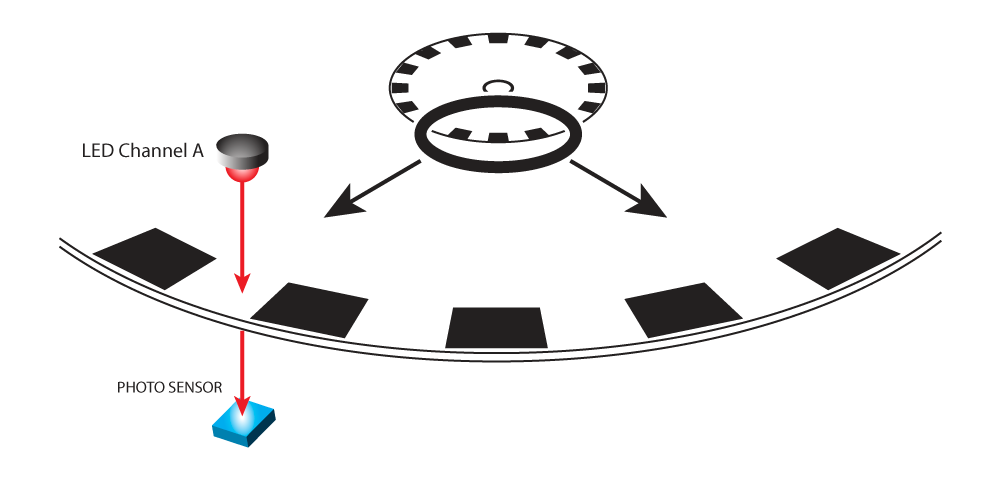
Each time the line passes between the LED and sensor, the wave drops from +5 Volts to 0 Volts, which gives us the waveform below:

Let’s add a bit more detail to that diagram to better explain quadrature:
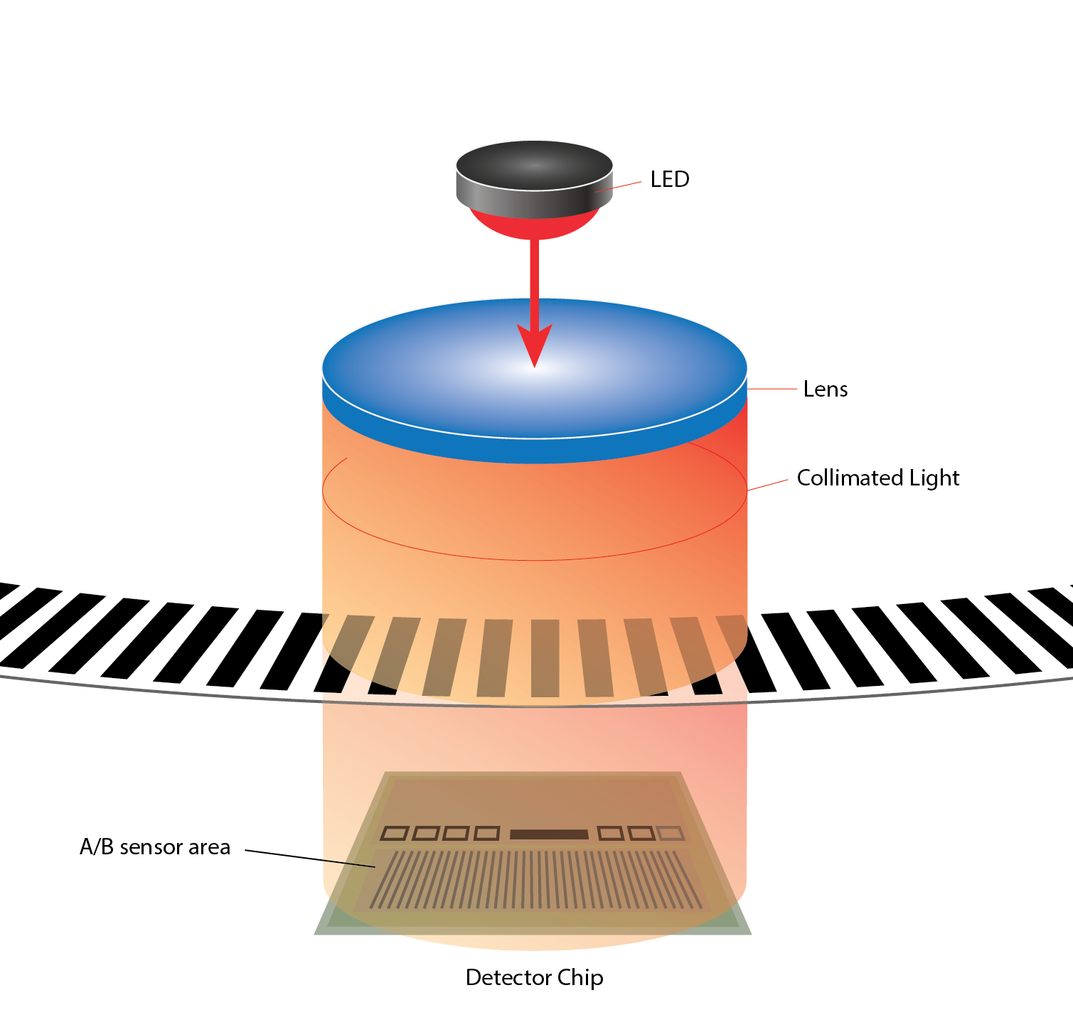
With our encoders, the LED light shines through a lens which focuses the light into a column, that column hits a chip on the other side of the disk with a photo detector area on it. Some parts of the detector area (sensors) are assigned to Channel A and others are assigned to Channel B. The chip is able to average out the pattern of light and dark to create a unique waveform for each channel using multiple sensors – but what exactly that means and its benefits is another blog post.
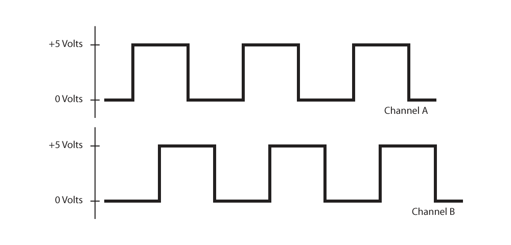
The sensors are aligned in such a way that Channel B is offset a quarter of an electrical cycle from Channel A. When you look at the waveforms for both channels on an oscilloscope, you see something like this:
Notice that Channel A goes high a little before Channel B. If we were to switch the direction of motion, Channel B would go high a little bit before Channel A does. Guess what? We can now detect direction of motion, based on which Channel is leading the other.
Get up to 4X CPR with quadrature
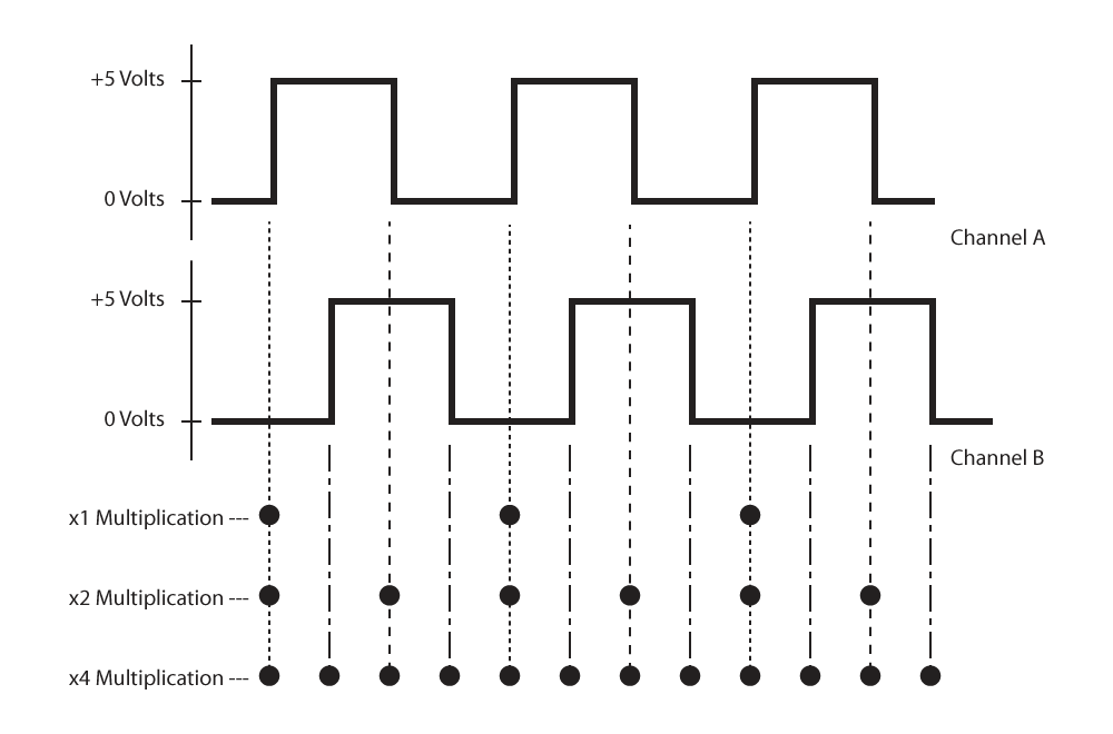
If you remember, an encoders resolution is equal to its Cycles Per Revolution (CPR). Although the number of lines printed on the disk is fixed, with quadrature you can get up to 4 times as many output pulses as the number of lines or windows.
This is known as resolution multiplication and can be accomplished with an encoder to counter interface chip such as our LS7183N. As an example, consider a 100-CPR encoder:
- x 1 – if we count the rising edge of each Channel A pulse as the disk rotates, we’ll get 100 pulses per revolution (100 PPR).
- x 2 – if we count each rising edge and each falling edge of Channel A, we’ll get 2 pulses per cycle, which adds up to 200 pulses per revolution (200 PPR).
- x 4 – if we count each rising edge and falling edge of both Channel A and Channel B, we’ll get 4 pulses per cycle, for a total of 400 pulses per revolution (400 PPR).
This technique of resolution multiplication can effectively double or quadruple the resolution of the encoder.
While a quadrature encoder can give you more counts per rotation and track direction of motion, it can’t help you return to a fixed location after a loss of power. If that is important for your application, you’re going to want to learn about an encoder’s Index Channel.
Looking for more information on encoders? Be sure to check out other posts on our blog and our YouTube Channel for more guides, tips and tutorials.
More in News
Stay up to date
Sign up for our newsletter to stay up to date with our product updates, blog posts, videos and white papers.