
How does an (incremental) encoder work?
Encoders can use a variety of technologies to turn physical motion into electrical data. In this post (and the above video) we look at how optical incremental encoders work.
Before we begin, we want to clarify that this is an oversimplified explanation of how our rotary incremental encoders work. If you want a more detailed explanation, check out our blog post on quadrature.
Our incremental encoder modules have an LED on one side and a photo sensor on the other. A HubDisk is attached to a shaft on a motor and aligned in such a way that its transparent disk passes between the LED and photo sensor in the module. A series of printed lines on the disk block light from the LED from reaching the sensor. The spaces between the lines do not.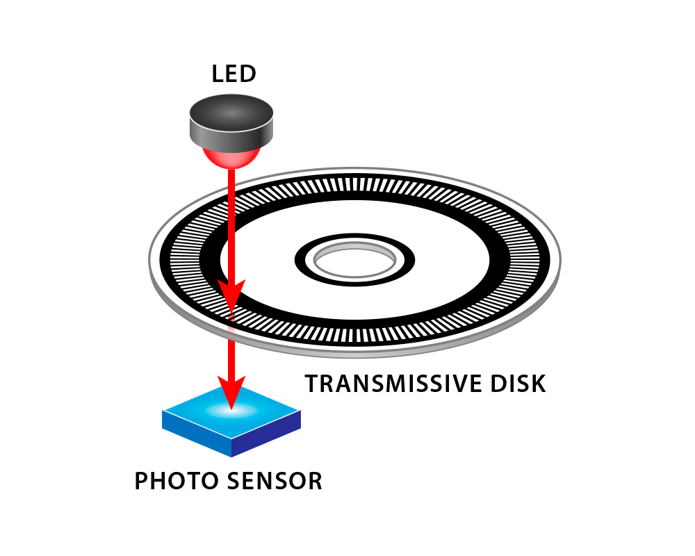
The pattern of light and dark is how an encoder reports information back to the mechanical system. The encoder reports 0 volts DC when light is blocked and 5 volts DC when light reaches the sensor. By connecting an oscilloscope to an encoder, you would see a pattern similar to this:
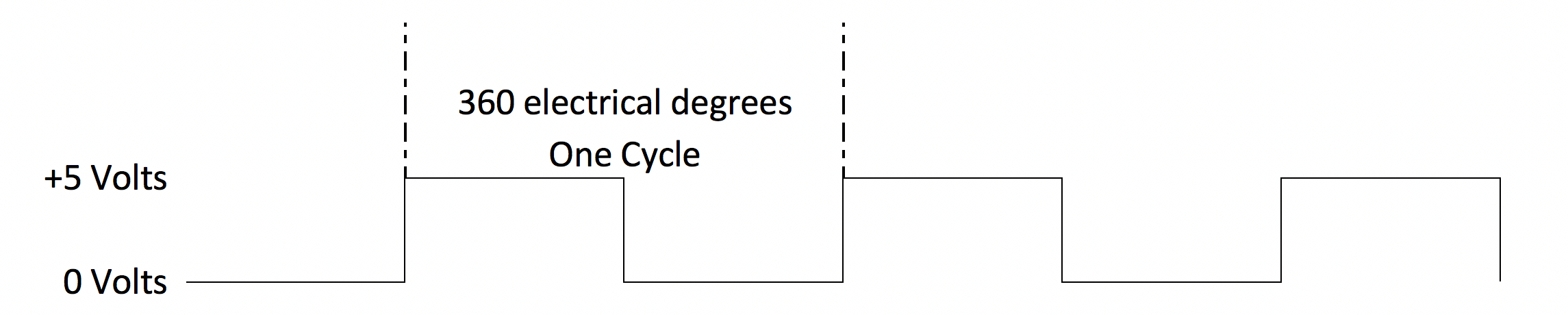
Encoders have a defined number of lines on each disk — this determines the resolution. The distance between lines represents a percentage of the disk’s rotation, and can be used to calculate speed, acceleration, direction, and position.
Regardless of what industry (or application), encoders are a great way to provide feedback you need to monitor and control physical movement.
More in News
Stay up to date
Sign up for our newsletter to stay up to date with our product updates, blog posts, videos and white papers.