

In earlier posts to this blog, we introduced incremental encoders in Encoders 009 and continued that discussion in Encoders 011, where we talked about Quadrature and Index. In today's post, we'll introduce another major category of encoders: Absolute Encoders.
Where Are We?
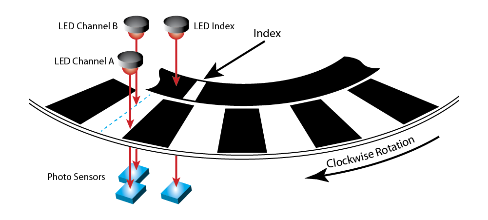
In our posts on incremental encoders, we developed a simplified picture showing essential components:
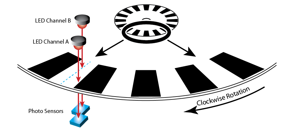
In the picture, the encoder has a resolution of 16 Cycles per Revolution (CPR). Two LEDs shine light at a transparent disk with 16 lines and 16 windows. When light shines through a window, the photo sensor on the other side outputs a signal that goes high. When the disk rotates and a line blocks the light, the signal goes low. As the disk moves through one rotation, the high/low cycle repeats 16 times—and then we're back where we started.
Let's look at just the disk, by itself.

Notice anything special about any particular line? That's right—nothing! There is nothing special about any of the lines. In fact, if we zoom in and take a closer look at one single line, and then the line 5 lines later, and another 6 lines after that, here is what we see –
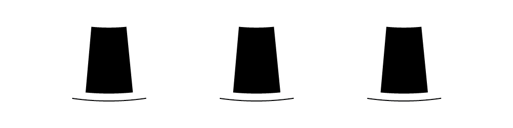
Each line looks like every other line; all the windows look the same. Even if we look closely at a line or window, we can't tell where it's located on the disk.
In applications that can use incremental encoders, this isn't a problem. We're mainly interested in the count as each line goes by the photo sensor. Applications that simply monitor speed or distance do just fine as each line passes; they don't need to know, "Hey! Which line was that that just went by?" They just need to start counting, and keep counting while the motion continues: "One, two, three…" and then a while later, "…nineteen, twenty, twenty-one…" and so on. For incremental encoders, what matters is the relative position—begin anywhere, move to the next position, and then the next…
But there are applications where we need to determine absolute position—and know exactly which part of the disk we're looking at.
Here We Are!
How can we find a specific location on an encoder disk? We could try numbering each line.

That works if the one doing the counting is a human—but our count is generated by an LED and photo sensor, and they can't read numbers, they can only read black and white; on and off; one and zero…
Hmm, that sounds familiar… ones and zeroes…. 1's and 0's… 0001, 0010… Let's try a different way of numbering our 16-sector disk.
We've created four bands. Each band represents a bit in a binary code, with the least significant bit on the outside rim. We've added an LED array, and photo sensors on the other side of the disk. Now when the disk rotates—or even if it's stopped—the sensors will output highs and lows, each determined by whether the band is black or transparent.
If we zoom in and look at three random positions, like we did with the incremental encoder, we might see something like this.
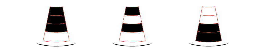
Which positions are they? No problem! In binary, left to right those are 0001, 0101, 1100 – or, in natural numbers, positions 1, 5 and 12.
We know where we are! I can now determine the absolute position of any location on the disk.
The Traditional Absolute Encoder
For a traditional absolute encoder, as we've shown it above, resolution is often expressed in bits, which refers to positions per rotation (also called codes per rotation). To increase resolution, manufacturers add a band for each bit. Here are two examples:
- 10-bit encoders have 10 bands, and can identify:
- 1,024 positions per revolution.
- 0.35° rotation angle per position
- 12-bit encoders have 12 bands, and can identify:
- 4,096 codes per revolution.
- 0.09° rotation angle per position
The encoder disk from our exercise above, with its 16 positions, has 4-bit resolution and a 22.5° rotation angle per position.
Other patterns besides the one we've shown have been used to make traditional absolute encoders, but the concept remains the same: bands of black lines and transparent windows generate digital numbers.
12-bit Resolution in a Single Band
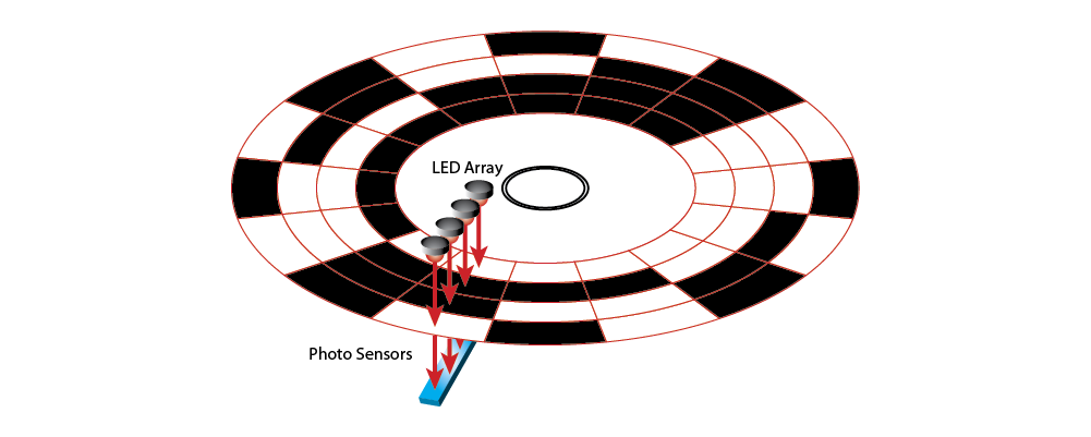
For a completely different way to create an absolute encoder, consider the single band with a bar code along the rim, used by some manufacturers.

The LED array and photo sensors are positioned along the circumference. As the disk rotates, the sensors see a unique bar code at each location.
An advantage of absolute encoders that employ bar codes is programmable resolution. The data sheet from one manufacturer, for example, shows a 12-bit absolute encoder whose resolution can be programmed anywhere from 2 to 4,096 positions per revolution. Users can select the best resolution for their application.
Pseudo-Absolute Encoders
At the end of our earlier post, "What is encoder index?", we introduced the Index feature for incremental encoders. Index is a single mark, located on its own band on the encoder disk.
With Index, you can identify a single location on the disk—and from that location, you can count and keep track of every other location. Using this technique, it's possible to operate an incremental encoder with index as a pseudo-absolute encoder.
Why the qualifying word 'pseudo'? Because you know where you are on the disk—but only until the power goes off. If there's a power failure, or you cycle power off and on, you will lose all position information. In that event, your system will need to perform a homing move to find the index position, and then start counting from that point.
Single-Turn versus Multi-Turn
Everything we've said so far has been about finding your location within a single revolution of the disk. What happens when the disk keeps rotating? That depends on which type of absolute encoder you have.
- Single-Turn Absolute Encoders : will restart the count and begin from zero for each rotation.
- Multi-Turn Absolute Encoders : will retain position information for additional rotations.
There is usually a limit to the number of turns a multi-turn encoder will keep track of.
When Do You Need an Absolute Encoder?
Incremental encoders are less expensive than absolute encoders, so to save costs most users will choose incremental encoders. But for some applications, an absolute encoder is the only solution. How do you tell the difference?
It comes down to this: in your system, if you power off and then power back on, do you need to know where you are (the shaft angle) after the power cycles?
- If you can move your system to a home position, find an index, and restart from there – you don't need an absolute encoder
- If you need to know where you are right away, and cannot move your system to a home position first—then you need an absolute encoder
An absolute encoder will tell you where you are, with no need for motion beforehand.
In this post, we've used optical encoders for illustrative purposes, but absolute encoders are also available in other encoder technologies (some of which we'll address in our next post), such as magnetic and capacitive. The same requirements for distinctive reporting apply to those technologies as well.
Coming Up in Absolute Encoders…
In this post, we've seen a few different ways to create an encoder disk that generates unique, absolute positions. But what do the output waveforms look like? We saw with incremental encoders that their output waveform is a series of high and lows, +5V and 0V. How about absolute encoders? We'll discuss that soon, when we continue this topic in Absolute Encoders – Part 2.
It is our goal to make this blog as informative, engaging and as accurate as possible. If you ever have some additional or contrary information, please contact us directly and we will be glad to make any appropriate corrections in a future post. Previous Post
More in News
Stay up to date
Sign up for our newsletter to stay up to date with our product updates, blog posts, videos and white papers.
Published in
News >
Blog