EPOT VOLTAGE-TO-QUADRATURE OR VOLTAGE-TO-STEP/DIRECTION CONVERTER

EPOT Features

  • Analog voltage to quadrature or analog voltage to step and direction outputs
  • Selectable velocity or position output mode
  • Adjustable dead band
  • Scalable output range
  • Single-ended or differential outputs

See more info below

Configure the EPOT

The EPOT is no longer available for purchase.

EPOT Product Description

The EPOT converts an analog voltage into digital encoder signals. The output signals may be configured to produce either an A/B quadrature output or step/direction output. The encoder signals may be further configured to provide velocity or position outputs proportional to the analog input voltage.

The single-ended output version is typically used with cables of 10 feet or less. For longer cable lengths, the differential output version is recommended. The internal differential line driver (26C31) can source and sink 20mA at TTL levels for differential versions. The recommended receiver is industry standard 26C32. Maximum noise immunity is achieved when the differential receiver is terminated with a 150 Ω resistor in series with a .0047 μF capacitor placed across each differential pair. The capacitor conserves power; otherwise, power consumption would increase by approximately 20mA per pair or 60mA for 3 pairs.

When the outputs of the EPOT are fed into a microstepping motor driver (see the MD2S datasheet), you can then use any analog voltage source such as a joystick or potentiometer to control the speed and direction of a motor.

Product Specifications

View here or download the specifications

SPECIFICATIONS

PARAMETER MIN. TYP. MAX. UNITS
Supply Voltage 4.5 5.0 5.5 V
Current Consumption   14   mA
Vout High (source 20 mA) 2.4 3.4   V
Vout Low  (sink 20 mA)   0.2 0.4 V
External Potentiometer Value 50     Ohms
Operating Temperature 0   70 C

TIMING SPECIFICATIONS

Analog Input Slew Rate:

PARAMETER MIN. TYP. MAX. UNITS
Position Output Mode: -2047 to 2047     73 V/sec
Position Output Mode: -1023 to 1023     200 V/sec
Position Output Mode: All Other     Unlimited V/sec

Output Settling Time in Response to a Full Scale Analog Input Step Transition:

PARAMETER MIN. TYP. MAX. UNITS
Position Output Mode:-2047 to 2047   160 (note 1)   ms
Position Output Mode:-1023 to 1023   100 (note 2)   ms
Position Output Mode: 511 to 511   105   ms
Position Output Mode: 255 to 255   65   ms
Position Output Mode: 127 to 127   80   ms
Position Output Mode: 63 to 63   75   ms
Position Output Mode: 31 to 31   45   ms
Position Output Mode: 15 to 15   35   ms

Notes:
(1) The step input was slew rate limited to a 73 V/sec rise time
(2) The step input was slew rate limited to a 200 V/sec rise time

DIP SWITCH SETTINGS

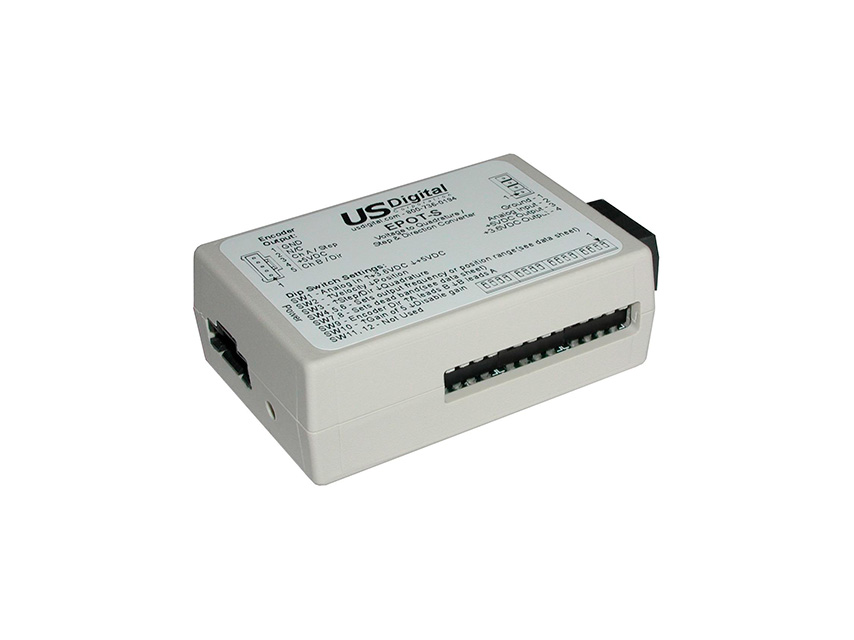
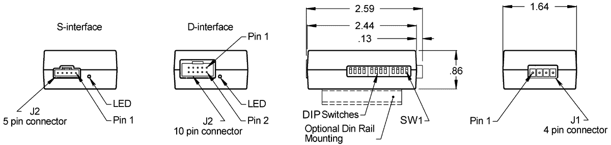
Note: After changing the DIP switch settings, the EPOT must be power cycled to ensure that the device configuration is updated.

DIP switch 1:

Selects the maximum analog input voltage. This voltage must match the output voltage used on connector J1.

↑ Up (1) position for +3.6V max. analog input
↓ Down (0) position for +5V max. analog input.

DIP switch 2:

Selects either velocity output mode or position output mode.

↑ Up (1) position for velocity output mode.
↓ Down (0) position for position output mode.

DIP switch 3:

Selects either quadrature output mode or step/direction mode.

↑ Up (1) position for step/direction output mode.
↓ Down (0) position for quadrature output mode.

DIP switches 4, 5 and 6:

Select the output frequency (for velocity output mode) or position range (for position output mode) as shown in the tables below.


SW4 SW5 SW6 POSITION OUTPUT MODE VELOCITY OUTPUT MODE
-15 to 15 counts 4.1KHz CCW to 4.1KHz CW
-31 to 31 counts 8.3KHz CCW to 8.3KHz CW
↓  -63 to 63 counts 16.6KHz CCW to 16.6KHz CW
↑  ↓  -127 to 127 counts 25.0KHz CCW to 25.0KHz CW
↓  ↓  -255 to 255 counts 33.3KHz CCW to 33.3KHz CW
↑  -511 to 511 counts 50.0KHz CCW to 50.0KHz CW
-1023 to 1023 counts 66.6KHz CCW to 66.6KHz CW
↑  ↑  -2047 to 2047 counts 100.0KHz CCW to 100.0KHz CW


DIP switches 7 and 8:

Selects the size of the dead band. The dead band is a selectable zero velocity output range. With human interface applications utilizing potentiometers or joysticks, it is difficult to return to a very precise zero velocity output location. A wider dead band makes it much easier to return a potentiometer or joystick to a zero-velocity point. This adjusts the width of the zero velocity dead band in the center of a potentiometer or joystick.


 SW7 SW8 DEAD BAND
0% (no dead band)
↑  2%
↑  4%
↑  ↑  6%


DIP switch 9:

Selects the encoder output direction. Moving this switch to the opposite state will change the direction output of the encoder signals.

   ↑ Up (1) position for normal direction on A and B.
   ↓ Down (0) position for reverse direction on A and B.

DIP switch 10:

Selects between a standard potentiometer and joystick style potentiometer. The typical total rotation seen by a potentiometer-based joystick is about 50 degrees. This switch adds a gain of 5 to enable the limited travel of a joystick potentiometer to produce a full-scale output from the EPOT. If a standard potentiometer is used with the EPOT, the gain should be disabled. If the gain is not disabled, the EPOT will reach a maximum value over about a 50-degree rotation of a standard potentiometer.

    ↑ Up (1) position to increase input gain by a factor of 5.
    ↓ Down (0) position to disable the gain increase.

DIP switch 11:

Selects which application is being used: potentiometer or joystick.

    ↑ Up (1) position for potentiometer applications.
    ↓ Down (0) position for joystick applications.

DIP switch 11 is only active when the EPOT is set up in velocity output mode. This switch determines how the EPOT will detect the zero-velocity position of the potentiometer or joystick attached to its analog input. The Up (1) position will calculate a midpoint location which provides zero velocity output when power is applied. The Down (0) position will assume the potentiometer or joystick is located in its midpoint or zero velocity position when power is applied

PIN-OUTS

J1 Connector Pin-out:

 PIN DESCRIPTION 
 1 Ground 
 2  Analog voltage input
 3  +5VDC output
 4  +3.6VDC regulated output

J2 Pin-out (Single-ended version):


PIN DESCRIPTION
1 Ground
2 NC
3 A output / Step output
4 +5VDC input power
5 B output / Direction output


J2 Pin-out (Differential output version):


PIN DESCRIPTION
1 Ground
2 Ground
3 NC
4 NC
5 A- output / Step- output
6 A+ output / Step+ output
7 +5VDC input power
8 +5VDC input power
9 B- output / Dir- output
10 B+ output / Dir+ output

PRODUCT CHANGE NOTIFICATIONS

Title Date Description Download
PCN 1011 9/21/2011 The AD2B, AD4B, AD7, EADAPT, EDAC2, EDIVIDE, EPOT, EQUAD, ESUM, ESWITCH, ETACH2, SEI-USB, USB-232 currently utilizes a printed thermal transfer label. This label will no longer be used and will be replaced by laser marking directly onto the housing of the product. The purpose for this change is to create a more durable solution, and eliminate the possibility of the label being inadvertently removed from the housing. Download
EOL EPOT - PCN 1024 6/17/2013 This PCN is a formal notification that US Digital is discontinuing the EPOT. Download

Additional Information

Product Notes

  • Cables and connectors are not included and must be ordered separately.
  • US Digital® warrants its products against defects in materials and workmanship for two years. See complete warranty for details.

Datasheets


Feedback

US Digital's mission is a commitment to quality and constant improvement. If you find an error to a product on this page, please let us know!