


SEI Serial Encoder Interface Bus
SEI Serial Encoder Interface Bus Data Sheet
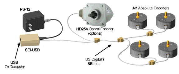
US Digital's SEI bus is a simple, quick, and convenient way of networking SEI encoders to a USB port of a standard Windows computer using an SEI-USB adapter and simple cabling. The SEI-USB is able to power a handful of encoders while drawing current from the USB port; a wall-mount PS-12 power supply is available to furnish the power for networks with a large number of devices on the SEI bus.
SEI Network
Interface
The SEI bus can support 1 to 15 devices on the SEI bus. For small networks (less than 40 feet of cable) the network topology can be a chain, star, or a combination of both; for larger/longer networks the daisy chain topology is preferred. SEI networks do not require cable terminations.
The bidirectional data lines carry commands and responses between the SEI-USB adapter connected to the host computer and the SEI device(s). The format is 1 start bit, 8 data bits, and 1 stop bit. The baud rate can be changed, but it always starts as 9600 baud after reset or power-up. Since the data bus is bidirectional, the host must release the bus within 20 uSec after the last command byte to avoid contention with the device's response. The SEI-USB adapter does this automatically, and it biases these lines with pull-up/down resistors to keep them in the inactive state when the bus is idle.
The busy lines are used for flow control. When a device is busy, it asserts these lines in an open collector fashion by driving Busy- low and Busy+ high. The SEI-USB adapter biases these lines at the host with pull-up/down resistors to keep them in the unasserted state (Busy+ with a resistor to ground, Busy- with a resistor to +5V) when they are not driven; networks that are not being driven by an SEI-USB will need to supply their own termination resistors. The Busy+ and Busy- lines are driven by the device which has been addressed as an acknowledgment of the command. They stay asserted until the command is completed. While a device drives the busy line, all other devices on the bus ignore the data flow. If a single device is on the bus, the busy lines can be ignored and pulled to the unasserted state, but it is easier to communicate with it if they are connected.
The maximum cable length from the SEI adapter to any device should be limited to 1000 feet. If the baud rate used is higher than 19.2 kbaud, the length should be reduced proportionally, ie: 200 ft at 115 kbaud. Contact us for information about longer cables at high baud rates. The encoder input power supply requirement is 7.5 volts minimum, which should be considered carefully when long cables are used; a greater supply voltage may be necessary because of the voltage drop caused by the cable's resistance (a typical 26 AWG telephone cable is 40 Ohms per 1000 feet). For example, the SEI-USB adapter provides 8 volts worst case; this may or may not be sufficient, depending on the number of encoders and cable length. When longer cable lengths and/or larger numbers of encoders are connected a PS-12 external power supply is recommended since it will supply a regulated 12 volt output to power the encoders. See table below "Total Cable Length versus Number of Encoders (9600 Baud)."
DC Electrical Specifications
The minimum and maximum values in the table below apply over an operating temperature range. Typical values are specified at Vcc=12V and 25C.
| Parameter | Min. | Typ. | Max. | Units | Notes |
|---|---|---|---|---|---|
| Differential output voltage(DataL - DataH), (Busy+ - Busy-) | 2 | - | 5 | Volts | Load = 100 Ohms |
| Differential input voltage (DataL - DataH), (Busy+ - Busy-) |
0.2 | - | 5 | Volts | |
| Common mode input voltage (DataH+DataL)/2, (Busy-+Busy+)/2 |
2.0 | 2.5 | 3 | Volts | Load = 100 Ohms |
| Common mode input voltage (DataH+DataL)/2, (Busy-+Busy+)/2 |
-4.5 | - | 3 | Volts |
AC Electrical Specifications
| Symbol | Description | Min. | Max. | Units | Note |
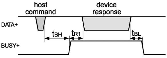
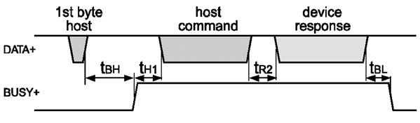
| TBH | Host command to busy active | 0.01 | 1 | mSec | 1 |
| TR1 | Encoder response time (1 byte command) | 0.01 | 1 | mSec | - |
| TR2 | Encoder response time (Mult. byte command) | 0.01 | 30 | mSec | 2 |
| TBL | Busy release time | 0.01 | 0.1 | mSec | - |
| TH1 | Host response time | 0 | 300 | mSec | 3 |
Single Byte Command Diagram
Multi Byte Command Diagram
Functional Pin Description
| Pin | Name | Description |
| 1 | GND | Ground, common for power, data, and busy pairs. |
| 2 | Busy+ Analog+ |
SEI version: bidirectional differential acknowledges line, active high (open-source output, must be pulled down to ground). Analog version: positive analog voltage output. |
| 3 | Busy- Analog- |
SEI version: bidirectional differential acknowledges line, active low (open-drain output, must be pulled up to +5 Volt). Analog version: analog signal ground, connected to GND pin. |
| 4 | PWR | Power supply input. |
| 5 | DataL | Bidirectional differential data line, non-inverted, and is pulled high through a 10k-ohm resistor to pin 4 PWR. |
| 6 | DataH | Bidirectional differential data line, inverted, and is pulled low through a 10k-ohm resistor to pin1 GND. |
Total Cable Length versus Number of Encoders (9600 Baud)
| Devices | 26 AWG cable | 28 AWG cable |
| 1 | 1000 ft | 1000 ft |
| 2 | 1000 ft | 640 ft |
| 3 | 670 ft | 420 ft |
| 5 | 400 ft | 250 ft |
| 10 | 200 ft | 125 ft |
| 15 | 125 ft | 80 ft |
Caution: Do not use voice-type telephone cables; they commonly reverse the pin-out which WILL damage the encoders on the network. The device network requires six wires straight (pin 1 to pin 1). We offer appropriate cables (26 AWG) of any length.
General Notes
- The lines busy+ and busy- are differential, and they should not be terminated.
- The lines dataL and dataH are RS485-type differential lines. They don't need to be terminated for cables up to 1000 ft long at 19.2 kbaud (proportionally shorter at higher baud rates, i.e. 200 ft at 115 kbaud). If terminated, make sure the lines are biased such that dataL is above dataH by at least 2 volts.
- For implementations with long cables or several devices on the bus, the supply voltage at the host should be appropriately higher to compensate for voltage losses in the wires.
- A "star" bus topology is discouraged, better performance may be obtained from a "daisy-chain" bus topology.