H3 Features
- Shafted ball bearing rotary encoder
- 20 Resolutions from 64 to 10,000 CPR (256 to 40,000 PPR)
- 1/4 in. diameter brass shaft mounted in 2 ball bearings
- 2 channel quadrature output with an optional index channel
- High retention connector/cable (sold separately)
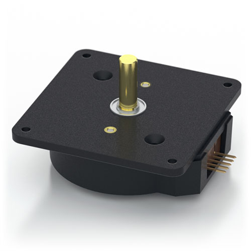
US Digital H3 Rotary Shaft Encoder Description
The H3 ball-bearing rotary encoder converts shaft position or speed into a quadrature output signal. This rotary encoder delivers up to 40,000 PPR resolution in a glass-filled polymer housing. The brass shaft rotates on a pair of ball bearings.
The H3 optical rotary encoder is designed to drive cables up to 10 feet long. For longer cable lengths, we recommend using the model H6 and selecting the differential output. Another option is to add a PC4/PC5 differential line driver to this encoder.
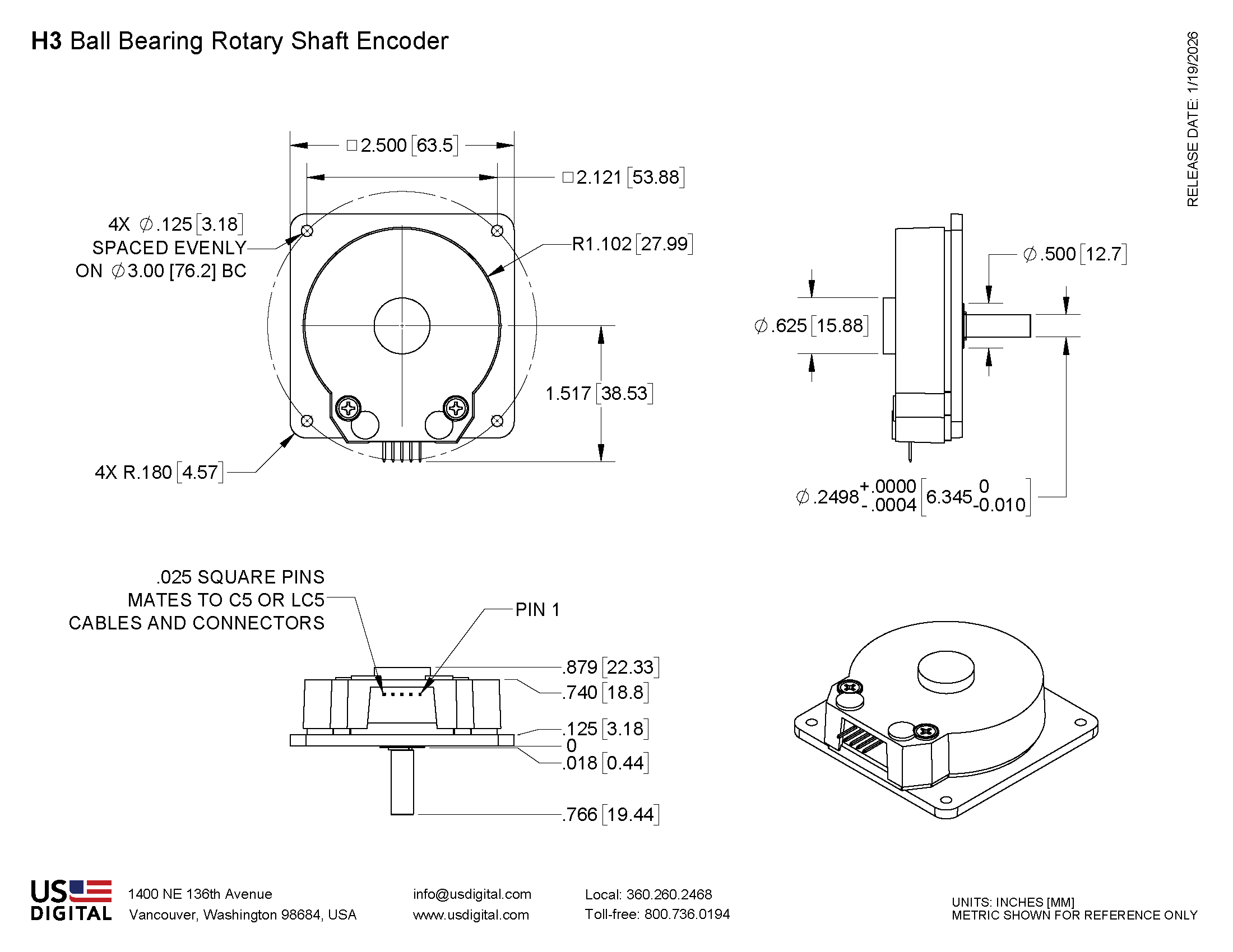
Mechanical Drawings
Specifications
ENVIRONMENTAL
| PARAMETER | VALUE | UNITS |
|---|---|---|
| Operating Temperature, CPR < 2000 | -40 to 100 | C |
| Operating Temperature, CPR ≥ 2000 | -25 to 100 | C |
| Electrostatic Discharge, IEC 61000-4-2 | ± 4 | kV |
| Vibration (10Hz to 2kHz, sinusoidal) | 20 | G |
| Shock (6 milliseconds, half-sine) | 75 | G |
MECHANICAL
| PARAMETER | VALUE |
|---|---|
| Max. Acceleration | 100000 rad/sec² |
| Max. Shaft Speed (mechanical) | 10000 RPM (1) |
| Max. Shaft Torque | 0.05 in-oz |
| Max. Shaft Loading | 2 lbs. |
| Bearing Life | life in millions of revs = (90/P)³ where P = radial load in pounds. |
| Weight | 2.69 oz. |
| Max. Shaft Runout | 0.006 in. T.I.R. |
| Mounting Plate Screw Torque | (#2-56) 2-3 |
| Moment of Inertia | 0.001 oz-in-s² |
| Technical Bulletin TB1001 - Shaft and Bore Tolerances | Download |
(1) The maximum speed due to electrical considerations is dependent on the CPR. See the EM1 and EM2 product pages.
PHASE RELATIONSHIP
B leads A for clockwise shaft rotation, and A leads B for counterclockwise rotation when viewed from the shaft side of the encoder.
ELECTRICAL
- Specifications apply over the entire operating temperature range.
- Typical values are specified at Vcc = 5.0Vdc and 25°C.
- For complete details, see the EM1 and EM2 product pages.
| PARAMETER | MIN. | TYP. | MAX. | UNITS | CONDITIONS |
|---|---|---|---|---|---|
| Supply Voltage | 4.5 | 5.0 | 5.5 | V | |
| Supply Current | 27 54 72 |
33 62 85 |
mA mA mA |
CPR < 1000, no load CPR ≥ 1000 and < 3600, no load CPR ≥ 3600, no load |
|
| Low-level Output | 0.05 0.25 |
0.5 0.5 |
V mA mA mA |
IOL = 8mA max., CPR < 3600 IOL = 5mA max., CPR ≥ 3600 no load, CPR < 3600 no load, CPR ≥ 3600 |
|
| High-level Output | 2.0 2.0 |
4.8 3.5 |
V V V V |
IOH = -8mA max., CPR < 3600 IOH = -5mA max., CPR ≥ 3600 no load, CPR < 3600 no load, CPR ≥ 3600 |
|
| Output Current Per Channel | -8 -5 |
8 5 |
mA mA |
CPR < 3600 CPR ≥ 3600 |
|
| Output Rise Time | 110 50 |
nS nS |
CPR < 3600 CPR ≥ 3600 |
||
| Output Fall Time | 35 50 |
nS nS |
CPR < 3600 CPR ≥ 3600 |
PIN-OUT
| PIN | DESCRIPTION |
|---|---|
| 1 | Ground |
| 2 | Index |
| 3 | A channel |
| 4 | +5VDC power |
| 5 | B channel |
Notes
- Cables and connectors are not included and must be ordered separately.
- US Digital® warrants its products against defects in materials and workmanship for two years. See complete warranty for details.
Configuration Options |
|||||||||||||||||||||||||||||
| H3 | - | CPR (Cycles Per Revolution) 64 100 200 400 500 512 1000 1024 1800 2000 2048 2500 3600 4000 4096 5000 7200 8000 8192 10000 | - | Index IE (Index) NE (Non-Index) | - | Housing D (Default) | |||||||||||||||||||||||
|
PLEASE NOTE: This chart is for informational use only. Certain product configuration combinations are not available. Visit the H3 product page for pricing and additional information. |
|||||||||||||||||||||||||||||