HD25 Features
- NEMA size 25 package
- 20 Resolutions from 64 to 10,000 CPR (256 to 40,000 PPR)
- Single-ended and differential outputs are available in low and high-voltage
- Optional Index channel
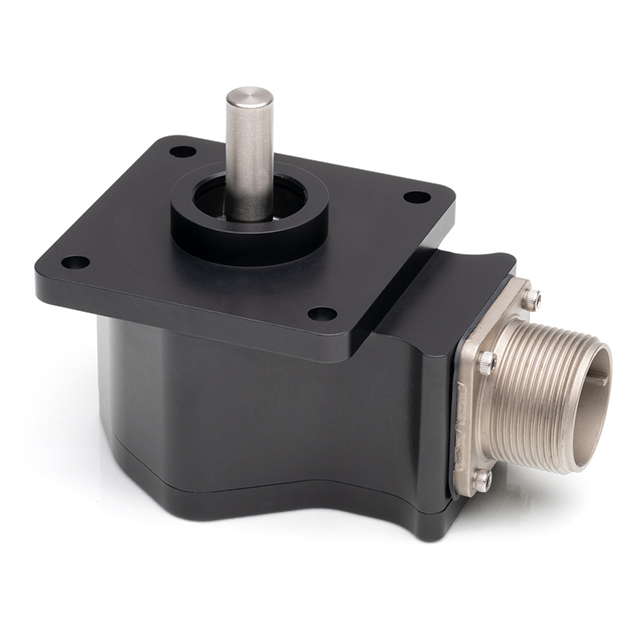
- Anodized black aluminum housing with stainless-steel shaft
- Sealed IP65 option
- Cable with military spec connector (sold separately)
US Digital HD25 Rotary Encoder Description
The HD25 is a rugged optical shaft encoder engineered for heavy-duty industrial applications and environments. Its machined aluminum housing, milled from a solid billet and black anodized for protection, conforms to the industry-standard Size 25 package and serves as a direct drop-in replacement for similar encoders.
This rotary encoder can be configured with or without a shaft flat and is available in sealed (IP65) or non-sealed versions. It provides single-ended or differential outputs, each offered in low-voltage (4.5-5.5 VDC) or high-voltage (9.5-30 VDC) signal levels, with an optional index channel. For cable runs longer than 10 ft or installations subject to electrical noise, the differential output is recommended for improved signal integrity.
The HD25 incremental encoder uses a military-spec screw-on connector. After you make your selections in the Product Configurator, compatible cables and connectors will be displayed below and must be ordered separately.
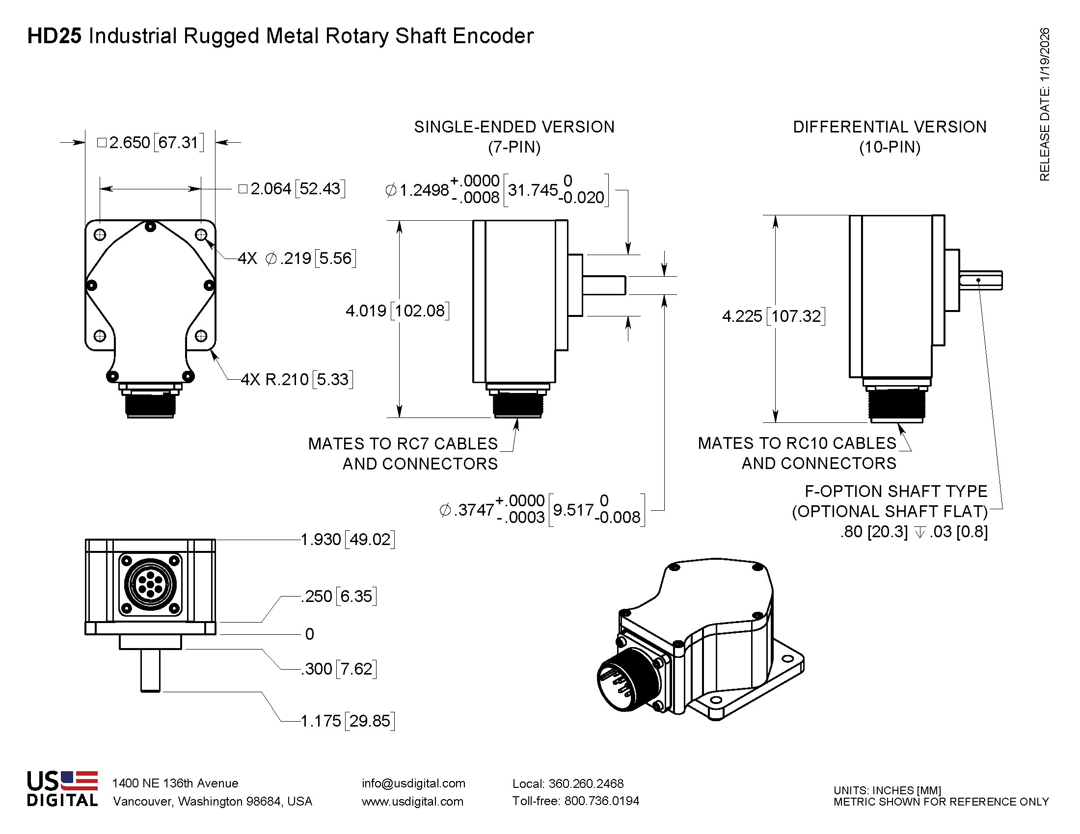
Mechanical Drawings
Specifications
ENVIRONMENTAL
| Parameter | Value |
|---|---|
| Operating Temperature Low voltage version, CPR < 3600 High voltage version, CPR < 3600 Low voltage version, CPR ≥ 3600 High voltage version, CPR ≥ 3600 |
-40C to 100C -40C to 85C -25C to 100C -25C to 85C |
| Humidity Non-sealed Sealed |
98% non-condensing 100% condensing (NEMA IP65) |
| Vibration (10 to 2kHz, sinusoidal) | 20G |
| Shock (6 milliseconds, half-sine) | 75G |
| Electrostatic Discharge Single-ended (-S version), IEC 61000-4-2 Differential (-D version), Human Body Model |
± 4 kV ± 2 kV |
MECHANICAL
| Parameter | Value |
|---|---|
| Size | NEMA size 25 |
| Housing and Cover Material | Anodized aluminum |
| Shaft Material | Stainless steel |
| Weight | 17 oz. |
| Shaft Diameter | 0.3748 in. (+0.0000 in. -0.0003 in.) |
| Shaft Optional Flat Size | .08 in. long x .03 in. deep |
| Max. Acceleration | 100000 rad / sec² |
| Max. Shaft Speed (1) Non-sealed (mechanical) Sealed (mechanical) |
15000 rpm 6000 rpm |
| Shaft Torque Non-sealed Sealed |
< 0.5 in-oz 3.5 in-oz typical |
| Max. Shaft Load Axial Radial |
40 lb. 35 lb. |
| Max. Shaft Runout | 0.0003 in. T.I.R. |
| Bearing Life @ 4 Pound Load | 2.3 x 10^9 revolutions |
| Moment of Inertia | 2.8 x 10^-4 oz-in-sec² |
| Technical Bulletin TB1001 - Shaft and Bore Tolerances | Download |
(1) The maximum speed due to electrical considerations is dependent on the CPR. See the EM1 and EM2 product pages.
PHASE RELATIONSHIP
B leads A for clockwise shaft rotation, and A leads B for counterclockwise rotation viewed from the shaft side of the encoder.
ELECTRICAL
- Specifications apply over the entire operating temperature range.
- Typical values are specified at 25°C.
- Output driver IC: ET7272B
- For complete details, see the EM1 and EM2 product pages.
| PARAMETER | MIN. | TYP. | MAX. | UNITS | CONDITIONS |
|---|---|---|---|---|---|
| Supply Voltage (Vs) Low Voltage Version High Voltage Version |
4.5 9.5 |
5.0 |
5.5 30 |
V |
|
| Supply Current | 138 | mA | |||
| Low-level Output | 0.4 | 0.5 | V | IOL = 20mA | |
| High-level Output | Vs - 2.0 | V | IOH = -20mA | ||
| Output Rise/Fall Time | 700 | 980 | nS |
7-PIN CONNECTOR PIN-OUT
| PIN | DESCRIPTION |
|---|---|
| A | A channel |
| B | B channel |
| C | Index |
| D | +VDC |
| E | Case ground |
| F | Common |
| G | NC |

10-PIN CONNECTOR PIN-OUT
| PIN | DESCRIPTION |
|---|---|
| A | A+ channel |
| B | B+ channel |
| C | Index+ |
| D | +VDC |
| E | NC |
| F | Common |
| G | Case ground |
| H | A- channel |
| I | B- channel |
| J | Index- |

Notes
- Cables and connectors are not included and must be ordered separately.
- US Digital® warrants its products against defects in materials and workmanship for two years. See complete warranty for details.
Configuration Options |
||||||||||||||||||||||||||||||||||||||||||
| HD25 | - | CPR (Cycles Per Revolution) 64 100 200 400 500 512 1000 1024 1800 2000 2048 2500 3600 4000 4096 5000 7200 8000 8192 10000 | - | Shaft Type N (Shaft without Flat) F (Shaft with Flat) | - | Shaft Seal N (Non-Sealed) S (Sealed) | - | Voltage L (Low Voltage) H (High Voltage) | - | Index IE (Index) NE (Non-Index) | - | Output S (Single-Ended) D (Differential) | ||||||||||||||||||||||||||||||
|
PLEASE NOTE: This chart is for informational use only. Certain product configuration combinations are not available. Visit the HD25 product page for pricing and additional information. |
||||||||||||||||||||||||||||||||||||||||||