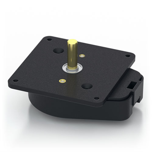
H6 Features
- Shafted ball bearing rotary encoder
- 20 Resolutions from 64 to 10,000 CPR (256 to 40,000 PPR)
- 1/4 in. diameter brass shaft mounted in 2 ball bearings
- Optional Index Channel, Differential, and High-Voltage Outputs
- Secure latching connector/cable (sold separately)
US Digital H6 Rotary Encoder Description
The H6 ball-bearing rotary encoder converts shaft position or speed into a quadrature output signal. This rotary encoder delivers up to 40,000 PPR resolution in a glass-filled polymer housing. The brass shaft rotates on a pair of ball bearings.
This optical rotary encoder features three output options: single-ended, single-ended High-Voltage, and differential. For differential versions, the internal line driver (26C31) can source and sink 20mA at TTL levels. The recommended receiver is the industry-standard 26C32.
The H6 incremental encoder is designed for use with a secure latching connector. After you make your selections in the Product Configurator, compatible cables and connectors will be displayed below and must be ordered separately.
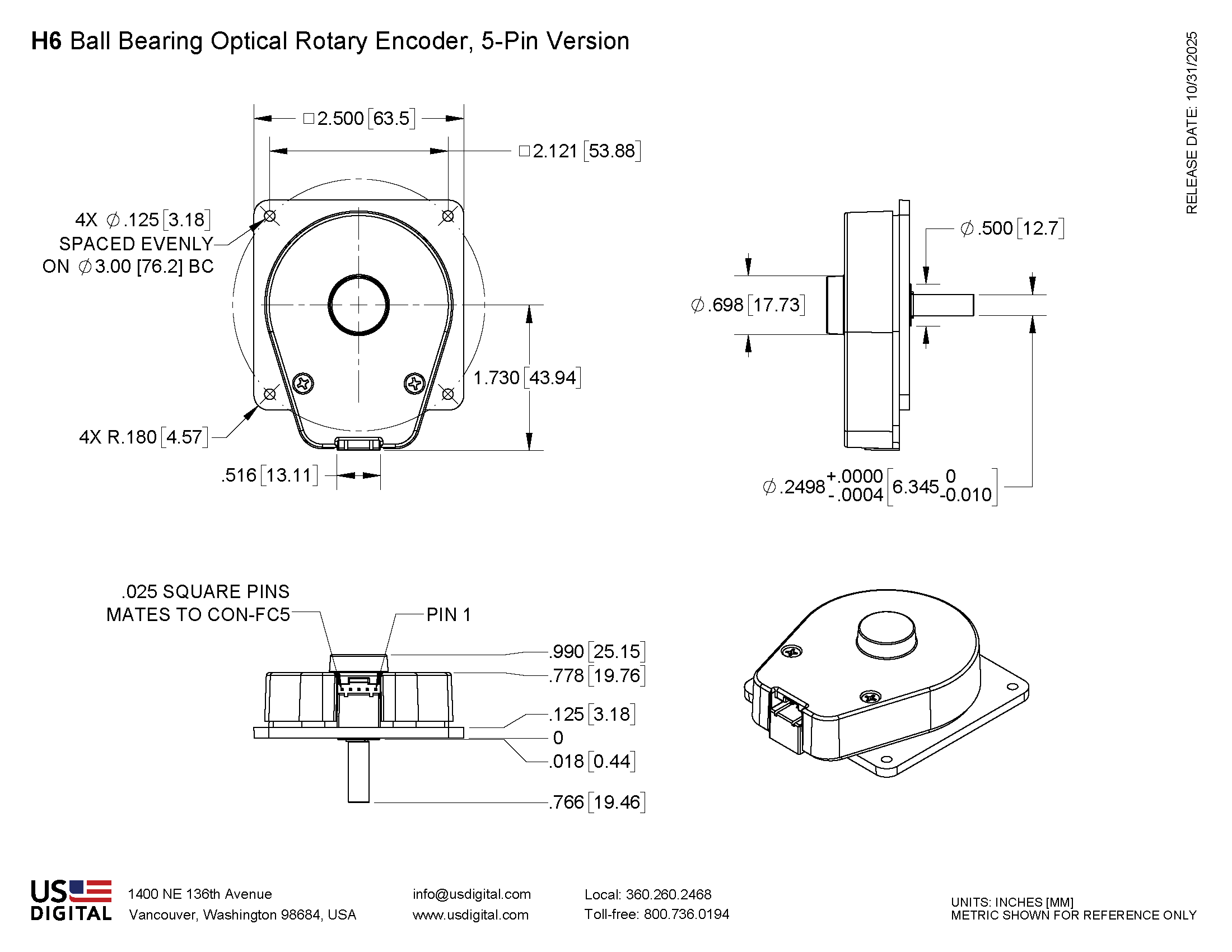
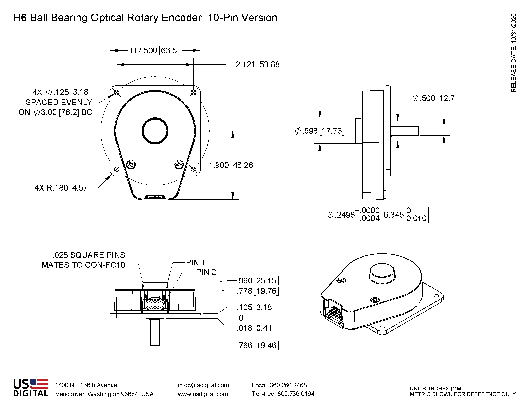
Mechanical Drawings
Specifications
ENVIRONMENTAL
| Parameter | Value | Units |
|---|---|---|
| Operating Temperature, CPR < 2000 | -40 to 100 | C |
| Operating Temperature, CPR ≥ 2000 | -25 to 100 | C |
| Electrostatic Discharge Single-ended (S option), IEC 61000-4-2 Differential (D, L option), Human Body Model High-Voltage, Open-collector (H, C option), IEC 61000-4-2 |
± 4 ± 2 ± 4 |
kV |
| Vibration (10Hz to 2kHz, sinusoidal) | 20 | G |
| Shock (6 milliseconds, half-sine) | 75 | G |
MECHANICAL
| PARAMETER | DIMENSION / UNITS |
|---|---|
| Max. Acceleration | 100000 rad/sec² |
| Max. Shaft Speed (mechanical) | 10000 rpm (1) |
| Max. Shaft Torque | 0.05 in-oz |
| Max. Shaft Loading | 2 lbs. |
| Bearing Life | life in millions of revs. = (90/P)³ where P = radial load in pounds. |
| Weight: Single-ended Differential High-Voltage, Open-Collector (H, C option) |
3.02 oz. 3.15 oz. 3.15 oz. |
| Max. Shaft Runout | 0.006 in. T.I.R. |
| Mounting Plate Screw Torque | (#2-56) 2-3 |
| Moment of Inertia | 0.001 oz-in-s² |
| Technical Bulletin TB1001 - Shaft and Bore Tolerances | Download |
(1) The maximum speed due to electrical considerations is dependent on the CPR. See the EM1 and EM2 product pages.
PHASE RELATIONSHIP
B leads A for clockwise shaft rotation, and A leads B for counterclockwise rotation when viewed from the shaft side of the encoder.
SINGLE-ENDED OPTION
- S option provides 5V TTL compatible outputs
- Specifications apply over the entire operating temperature range
- Typical values are specified at Vcc = 5.0Vdc and 25°C
- For complete details, see the EM1 and EM2 product pages
| PARAMETER | MIN. | TYP. | MAX. | UNITS | CONDITIONS |
|---|---|---|---|---|---|
| Supply Voltage | 4.5 | 5.0 | 5.5 | V | |
| Supply Current | 27 54 72 |
33 62 85 |
mA mA mA |
CPR < 1000, no load CPR ≥ 1000 and < 3600, no load CPR ≥ 3600, no load |
|
| Low-level Output | 0.05 0.25 |
0.5 0.5 |
V mA mA mA |
IOL = 8mA max., CPR < 3600 IOL = 5mA max., CPR ≥ 3600 no load, CPR < 3600 no load, CPR ≥ 3600 |
|
| High-level Output | 2.0 2.0 |
4.8 3.5 |
V V V V |
IOH = -8mA max., CPR < 3600 IOH = -5mA max., CPR ≥ 3600 no load, CPR < 3600 no load, CPR ≥ 3600 |
|
| Output Current Per Channel | -8 -5 |
8 5 |
mA mA |
CPR < 3600 CPR ≥ 3600 |
|
| Output Rise Time | 110 50 |
nS nS |
CPR < 3600 CPR ≥ 3600 |
||
| Output Fall Time | 35 50 |
nS nS |
CPR < 3600 CPR ≥ 3600 |
DIFFERENTIAL OPTION
- D Option provides differential line driver outputs
- Specifications apply over the entire operating temperature range
- Typical values are specified at Vcc = 5.0Vdc and 25°C
- For complete details, see the EM1 and EM2 product pages
| PARAMETER | MIN. | TYP. | MAX. | UNITS | CONDITIONS |
|---|---|---|---|---|---|
| Supply Voltage | 4.5 | 5.0 | 5.5 | V | |
| Supply Current | 29 56 74 |
36 65 88 |
mA mA mA |
CPR < 1000, no load CPR ≥ 1000 and < 3600, no load CPR ≥ 3600, no load |
|
| Low-level Output | 0.2 | 0.4 | V | IOL = 20mA max. | |
| High-level Output | 2.4 | 3.4 | V | IOH = -20mA max. | |
| Differential Output Rise/Fall Time | 15 | nS |
HIGH-VOLTAGE OPTION
- H option uses a higher supply voltage and provides both single-ended and open-collector outputs
- Single-ended outputs are 5V TTL compatible (same as S option). See Pin-out.
- Specifications apply over the entire operating temperature range
- For complete details, see the EM1 or EM2 product pages
| PARAMETER | MIN. | TYP. | MAX. | UNITS | CONDITIONS |
|---|---|---|---|---|---|
| Supply Voltage | 7.5 | 30.0 | V | ||
| Supply Current, 24V power | 8 16 22 |
10 19 25 |
mA mA mA |
CPR < 500, no load CPR ≥ 500 and < 2000, no load CPR ≥ 2000, no load |
|
| Open Collector "On" Resistance | 2 | ohms | |||
| Open Collector Sink Current | 200 | mA | |||
| Output Low Voltage | 0.4 | V | 200 mA sink current | ||
| Open Collector Pullup Voltage | 50 | V |
PIN-OUT
| 5-PIN SINGLE-ENDED | 10-PIN DIFFERENTIAL | 10-PIN HIGH-VOLTAGE H OPTION (2) |
|||
|---|---|---|---|---|---|
| Pin | Description | Pin | Description | Pin | Description |
| 1 | Ground | 1 | Ground | 1 | Ground |
| 2 | Index | 2 | Ground | 2 | Ground |
| 3 | A channel | 3 | Index- | 3 | Index- (open collector) |
| 4 | +5VDC power | 4 | Index+ | 4 | Index+ (single-ended) |
| 5 | B channel | 5 | A- channel | 5 | A- channel (open collector) |
| 6 | A+ channel | 6 | A+ channel (single-ended) | ||
| 7 | +5VDC power | 7 | 7.5-30V power | ||
| 8 | +5VDC power | 8 | 7.5-30V power | ||
| 9 | B- channel | 9 | B- channel (open collector) | ||
| 10 | B+ channel | 10 | B+ channel (single-ended) | ||
(1) 5-pin single-ended mating connector is CON-FC5.
(2) 10-pin differential mating connector is CON-FC10.
Notes
- Cables and connectors are not included and must be ordered separately.
- US Digital® warrants its products against defects in materials and workmanship for two years. See complete warranty for details.
Configuration Options |
|||||||||||||||||||||||||||||||
| H6 | - | CPR (Cycles Per Revolution) 64 100 200 400 500 512 1000 1024 1800 2000 2048 2500 3600 4000 4096 5000 7200 8000 8192 10000 | - | Index IE (Index) NE (Non-Index) | - | Output S (Single-Ended) H (Single-Ended High-Voltage) D (Differential) | |||||||||||||||||||||||||
|
PLEASE NOTE: This chart is for informational use only. Certain product configuration combinations are not available. Visit the H6 product page for pricing and additional information. |
|||||||||||||||||||||||||||||||