H3 Features
- Ball-bearing option tracks to 10,000 RPM
- 2-channel quadrature, TTL squarewave outputs
- 3rd channel index option available on some resolutions
- 64 to 10,000 cycles per revolution (CPR)
- 256 to 40,000 pulses per revolution (PPR)
- Wide operating temperature
- Single +5VDC supply
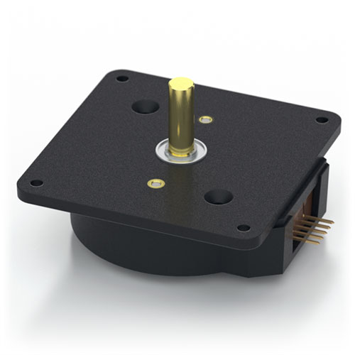
H3 Product Description
The H3 series ball-bearing optical shaft encoder has a glass-filled polymer enclosure. This non-contacting rotary to digital converter is designed to provide digital feedback information. The H3 is fully assembled with a brass shaft, two 1/4 in. ID by 1/2 in. OD ball bearings and a mounting plate. The mounting plate comes with 4 mounting holes for #2 - #4 size screws.
The H3 is designed to drive cables up to 10 feet long. For longer cable lengths, adding a PC4/PC5 differential line driver is recommended. A connection to the H3 series encoder is made through a 5-pin standard connector. The mating connectors are available from US Digital with several cable options and lengths.
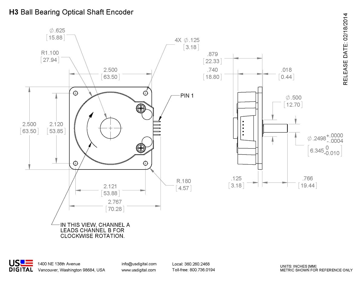
Mechanical Drawings
Specifications
ENVIRONMENTAL
| PARAMETER | VALUE | UNITS |
|---|---|---|
| Operating Temperature, CPR < 2000 | -40 to 100 | C |
| Operating Temperature, CPR ≥ 2000 | -25 to 100 | C |
| Electrostatic Discharge, IEC 61000-4-2 | ± 4 | kV |
| Vibration (10Hz to 2kHz, sinusoidal) | 20 | G |
| Shock (6 milliseconds, half-sine) | 75 | G |
MECHANICAL
| PARAMETER | VALUE |
|---|---|
| Max. Acceleration | 100000 rad/sec² |
| Max. Shaft Speed (mechanical) | 10000 RPM (1) |
| Max. Shaft Torque | 0.05 in-oz |
| Max. Shaft Loading | 2 lbs. |
| Bearing Life | life in millions of revs = (90/P)³ where P = radial load in pounds. |
| Weight | 2.69 oz. |
| Max. Shaft Runout | 0.006 in. T.I.R. |
| Mounting Plate Screw Torque | (#2-56) 2-3 |
| Moment of Inertia | 0.001 oz-in-s² |
| Technical Bulletin TB1001 - Shaft and Bore Tolerances | Download |
(1) The maximum speed due to electrical considerations is dependent on the CPR. See the EM1 and EM2 product pages.
PHASE RELATIONSHIP
B leads A for clockwise shaft rotation, and A leads B for counterclockwise rotation when viewed from the shaft side of the encoder.
ELECTRICAL
- Specifications apply over the entire operating temperature range.
- Typical values are specified at Vcc = 5.0Vdc and 25°C.
- For complete details, see the EM1 and EM2 product pages.
| PARAMETER | MIN. | TYP. | MAX. | UNITS | CONDITIONS |
|---|---|---|---|---|---|
| Supply Voltage | 4.5 | 5.0 | 5.5 | V | |
| Supply Current | 27 | 33 | mA | CPR < 1000, no load | |
| 54 | 62 | mA | CPR ≥ 1000 and < 3600, no load | ||
| 72 | 85 | mA | CPR ≥ 3600, no load | ||
| Low-level Output | 0.5 | V | IOL = 8mA max., CPR < 3600 | ||
| 0.5 | mA | IOL = 5mA max., CPR ≥ 3600 | |||
| 0.05 | mA | no load, CPR < 3600 | |||
| 0.25 | mA | no load, CPR ≥ 3600 | |||
| High-level Output | 2.0 | V | IOH = -8mA max., CPR < 3600 | ||
| 2.0 | V | IOH = -5mA max., CPR ≥ 3600 | |||
| 4.8 | V | no load, CPR < 3600 | |||
| 3.5 | V | no load, CPR ≥ 3600 | |||
| Output Current Per Channel | -8 | 8 | mA | CPR < 3600 | |
| -5 | 5 | mA | CPR ≥ 3600 | ||
| Output Rise Time | 110 | nS | CPR < 3600 | ||
| 50 | nS | CPR ≥ 3600 | |||
| Output Fall Time | 35 | nS | CPR < 3600 | ||
| 50 | nS | CPR ≥ 3600 |
PIN-OUT
| PIN | DESCRIPTION |
|---|---|
| 1 | Ground |
| 2 | Index |
| 3 | A channel |
| 4 | +5VDC power |
| 5 | B channel |
Notes
- Cables and connectors are not included and must be ordered separately.
- US Digital® warrants its products against defects in materials and workmanship for two years. See complete warranty for details.
Configuration Options |
|||||||||||||||||||||||||||||
| H3 | - | CPR (Cycles Per Revolution) 64 100 200 400 500 512 1000 1024 1800 2000 2048 2500 3600 4000 4096 5000 7200 8000 8192 10000 | - | Index IE (Index) NE (Non-Index) | - | Housing D (Default) | |||||||||||||||||||||||
|
PLEASE NOTE: This chart is for informational use only. Certain product configuration combinations are not available. Visit the H3 product page for pricing and additional information. |
|||||||||||||||||||||||||||||