E5 Features
- Kit version for mounting on a motor or other shaft
- Supports 14 shaft sizes (2 to 10 mm and 1/8 to 3/8 in.)
- For NEMA 17 to 34 and larger motors
- 25 Resolutions from 32 to 5,000 CPR (128 to 20,000 PPR)
- Optional Index channel, Differential and High-Voltage outputs
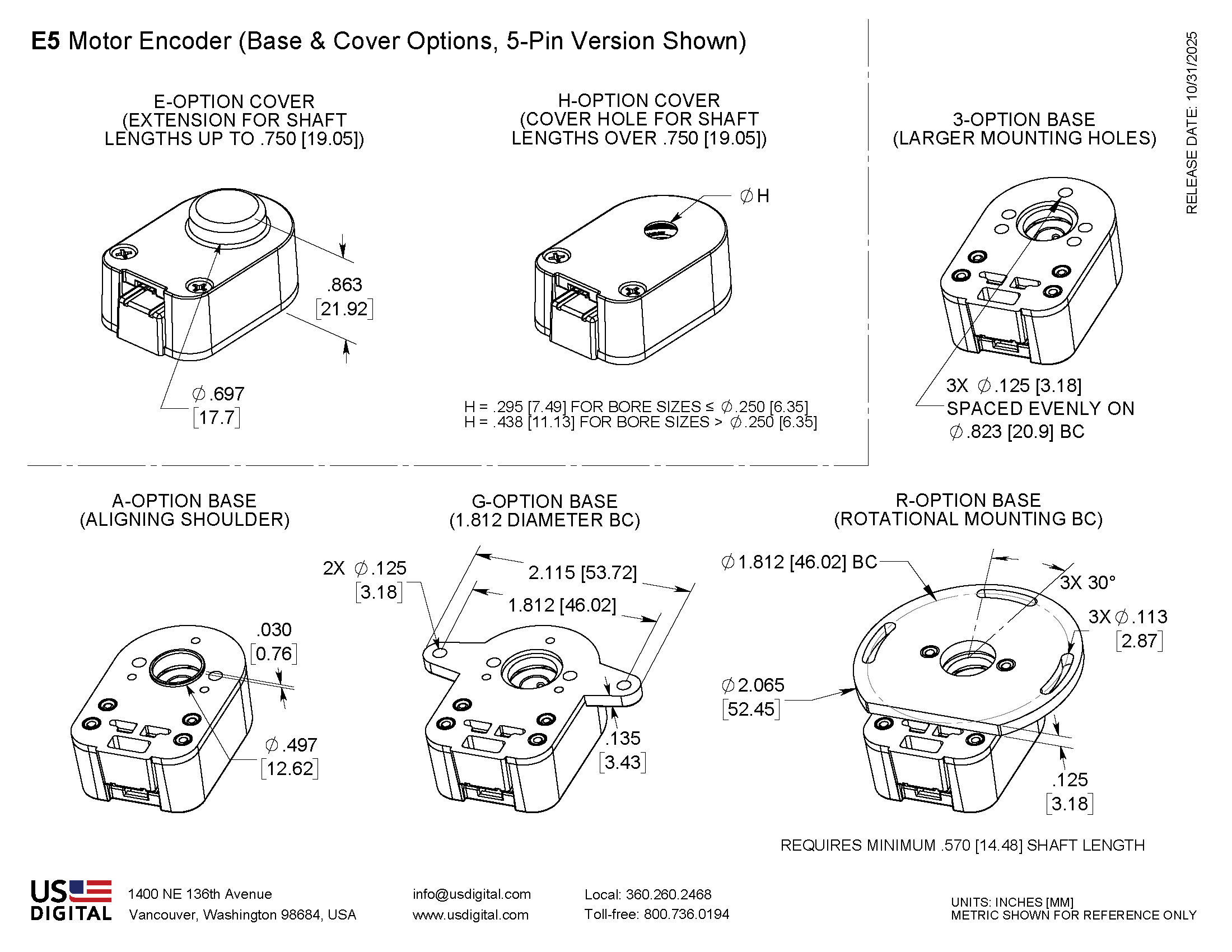
- Choice of 4 base styles and 3 cover options
- Secure latching connector/cable (sold separately)
US Digital E5 Motor Encoder Description
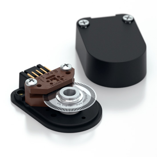
The US Digital E5 motor encoder mounts directly to a motor or other rotating shaft. This optical encoder features a rugged, glass-filled polymer housing and is designed for easy installation and removal.
The E5 encoder contains a precision machined aluminum hub with a specially patterned Mylar disk. This disk, in combination with our proprietary optical encoder module, creates a system that is highly tolerant to mechanical misalignment.
The E5 is a versatile motor encoder, with four base configurations and three cover styles which allows it to fit a wide range of applications. This optical rotary encoder also has four available outputs—single-ended, single-ended High-Voltage, differential, and Avago differential. This optical encoder is designed for use with a secure latching connector. After making each selection in the Product Configurator, compatible cables and connectors will be displayed below and must be purchased separately.
BROADCOM/AVAGO REPLACEMENTS:
US Digital's E5 encoder may be used as a replacement for Avago HEDL-5500, HEDL-5600.
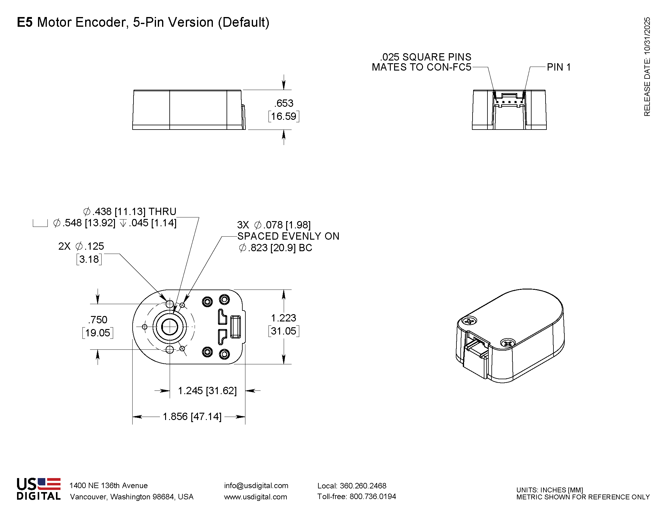
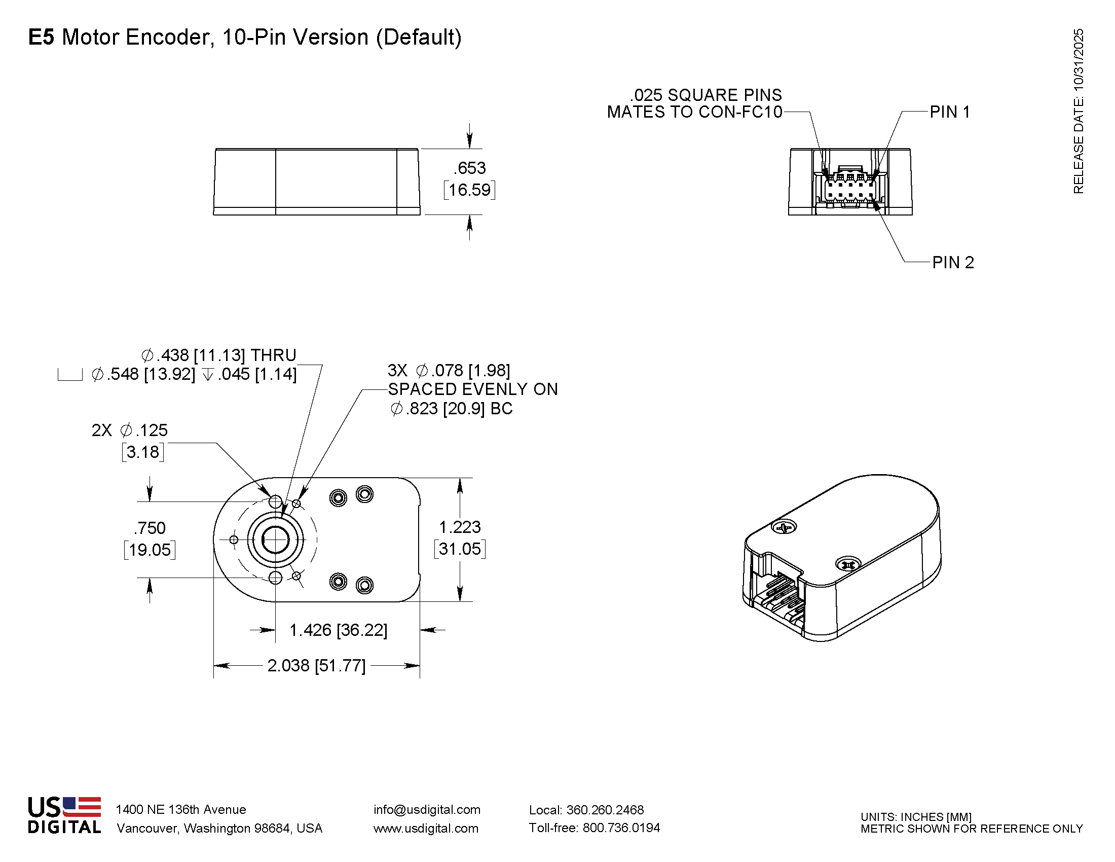
Mechanical Drawings
Specifications
ENVIRONMENTAL
| Parameter | Value | Units |
|---|---|---|
| Operating Temperature, CPR < 2000 | -40 to 100 | C |
| Operating Temperature, CPR ≥ 2000 | -25 to 100 | C |
| Electrostatic Discharge Single-ended (S option), IEC 61000-4-2 Differential (D, L option), Human Body Model High-Voltage, Open-collector (H, C option), IEC 61000-4-2 |
± 4 ± 2 ± 4 |
kV |
| Vibration (10Hz to 2kHz, sinusoidal) | 20 | G |
| Shock (6 milliseconds, half-sine) | 75 | G |
MECHANICAL
| PARAMETER | VALUE | UNITS |
|---|---|---|
| Max. Shaft Axial Play | ±0.010 | in. |
| Max. Shaft Runout | 0.004 T.I.R. | in. |
| Max. Acceleration | 250000 | rad/sec² |
| For CPR ≤ 1250: Max. RPM (1) Max. A/B Frequency e.x. CPR=1250, Max. RPM=14400 e.x. CPR=100, Max. RPM=60000 |
minimum value of ((18 x 10^6) / CPR) and (60000) 300 |
RPM kHz |
| For CPR = 2000, 2048, 2500: Max. RPM (1) Max. A/B Frequency |
minimum value of ((21.6 x 10^6) / CPR) and (60000) 360 |
RPM kHz |
| For CPR = 4000, 4096, 5000: Max. RPM (1) Max. A/B Frequency |
minimum value of ((43.2 x 10^6) / CPR) and (60000) 720 |
RPM kHz |
| Typical Product Weight Single-ended (S option) Differential (D, L option) High-Voltage, Open-Collector (H, C option) |
0.82 0.91 0.91 |
oz. |
| Codewheel Moment of Inertia | 8.0 x 10^-6 | oz-in-s² |
| Hub Set Screw | #4-48 | |
| Hex Wrench Size | 0.050 | in. |
| Encoder Base Plate Thickness | 0.135 | in. |
| 3 Mounting Screw Size | #0-80 | |
| 2 Mounting Screw Size | #2-56 or #4-40 | |
| 3 Screw Bolt Circle Diameter | 0.823 ± 0.005 | in. |
| 2 Screw Bolt Circle Diameter | 0.750 ± 0.005 | in. |
| Required Shaft Length (2) With E-option (2) With H-option (2) |
0.445 to 0.570 0.445 to 0.750 > 0.445 |
in. |
| Index Alignment to Hub Set Screw | 180 Typical | degrees |
| Technical Bulletin TB1001 - Shaft and Bore Tolerances | Download | |
(1) 60000 RPM is the maximum rpm due to mechanical considerations. The maximum rpm due to the module's maximum frequency response is dependent upon the module’s resolution (CPR).
(2) Add 0.125" to the required shaft length when using R-option.
TORQUE SPECIFICATIONS
| PARAMETER | VALUE | TORQUE |
|---|---|---|
| Hub Set Screw | 2-3 | in-lbs |
| Cover Screw | 2-4 | in-lbs |
| Base Mounting Screw (#0-80) | 1-2 | in-lbs |
| Base Mounting Screw (#2-56) | 2-3 | in-lbs |
| Base Mounting Screw (#4-40) | 4-6 | in-lbs |
| Adapter Plate Mounting Surface (#2-56 screws) | 2-3 | in-lbs |
| Adapter Plate Mounting Surface (#4-40 screws) | 4-6 | in-lbs |
| Module Mounting Screw | 3.5-4 | in-lbs |
PHASE RELATIONSHIP
SINGLE-ENDED (S) / DIFFERENTIAL (D) / HIGH-VOLTAGE (H) / OPEN-COLLECTOR (C) OPTION:
A leads B for clockwise shaft rotation, and B leads A for counterclockwise rotation as viewed from the cover side of the encoder.
BROADCOM/AVAGO COMPATIBLE PIN-OUT (L) OPTION:
B leads A for clockwise shaft rotation, and A leads B for counterclockwise rotation as viewed from the cover side of the encoder.
SINGLE-ENDED OPTION
- S option provides 5V TTL compatible outputs
- Specifications apply over the entire operating temperature range
- Typical values are specified at Vcc = 5.0Vdc and 25°C
- For complete details, see the EM1 or EM2 product pages
| PARAMETER | MIN. | TYP. | MAX. | UNITS | CONDITIONS |
|---|---|---|---|---|---|
| Supply Voltage | 4.5 | 5.0 | 5.5 | V | |
| Supply Current | 27 54 72 |
33 62 85 |
mA mA mA |
CPR < 500, no load CPR ≥ 500 and < 2000, no load CPR ≥ 2000, no load |
|
| Low-level Output | 0.25 |
0.5 0.5 |
V V V |
IOL = 8mA max., CPR < 2000 IOL = 5mA max., CPR ≥ 2000 no load, CPR ≥ 2000 |
|
| High-level Output | 2.0 2.0 |
4.8 3.5 |
V V V V |
IOH = -8mA max. and CPR < 2000 IOH = -5mA max. and CPR ≥ 2000 no load and CPR < 2000 no load and CPR ≥ 2000 |
|
| Output Current Per Channel | -8 -5 |
8 5 |
mA mA |
CPR < 2000 CPR ≥ 2000 |
|
| Output Rise Time | 110 50 |
nS nS |
CPR < 2000 CPR ≥ 2000, ± 5mA load |
||
| Output Fall Time | 100 50 |
nS nS |
CPR < 2000 CPR ≥ 2000, ± 5mA load |
DIFFERENTIAL OPTION
- D Option provides differential line driver outputs
- Specifications apply over the entire operating temperature range
- Typical values are specified at Vcc = 5.0Vdc and 25°C
- For complete details, see the EM1 or EM2 product pages
| PARAMETER | MIN. | TYP. | MAX. | UNITS | CONDITIONS |
|---|---|---|---|---|---|
| Supply Voltage | 4.5 | 5.0 | 5.5 | V | |
| Supply Current | 29 56 74 |
36 65 88 |
mA mA mA |
CPR < 500, no load CPR ≥ 500 and < 2000, no load CPR ≥ 2000, no load |
|
| Low-level Output | 0.2 | 0.4 | V | IOL = 20mA max. | |
| High-level Output | 2.4 | 3.4 | V | IOH = -20mA max. | |
| Differential Output Rise/Fall Time | 15 | nS |
HIGH-VOLTAGE OPTION
- H option uses a higher supply voltage and provides both single-ended and open-collector outputs
- Single-ended outputs are 5V TTL compatible (same as S option). See Pin-out.
- Specifications apply over the entire operating temperature range
- For complete details, see the EM1 or EM2 product pages
| PARAMETER | MIN. | TYP. | MAX. | UNITS | CONDITIONS |
|---|---|---|---|---|---|
| Supply Voltage | 7.5 | 30.0 | V | ||
| Supply Current, 24V power | 8 16 22 |
10 19 25 |
mA mA mA |
CPR < 500, no load CPR ≥ 500 and < 2000, no load CPR ≥ 2000, no load |
|
| Open Collector "On" Resistance | 2 | ohms | |||
| Open Collector Sink Current | 200 | mA | |||
| Output Low Voltage | 0.4 | V | 200 mA sink current | ||
| Open Collector Pullup Voltage | 50 | V |
PIN-OUTS
| 5-PIN SINGLE-ENDED S OPTION (1) |
10-PIN DIFFERENTIAL D OPTION (2) |
10-PIN DIFFERENTIAL L OPTION (2,3) |
10-PIN HIGH-VOLTAGE H OPTION (2) |
||||
|---|---|---|---|---|---|---|---|
| Pin | Description | Pin | Description | Pin | Description | Pin | Description |
| 1 | Ground | 1 | Ground | 1 | No Connection | 1 | Ground |
| 2 | Index | 2 | Ground | 2 | +5VDC power | 2 | Ground |
| 3 | A channel | 3 | Index- | 3 | Ground | 3 | Index- (open collector) |
| 4 | +5VDC power | 4 | Index+ | 4 | No connection | 4 | Index+ (single-ended) |
| 5 | B channel | 5 | A- channel | 5 | A- channel | 5 | A- channel (open collector) |
| 6 | A+ channel | 6 | A+ channel | 6 | A+ channel (single-ended) | ||
| 7 | +5VDC power | 7 | B- channel | 7 | 7.5-30V power | ||
| 8 | +5VDC power | 8 | B+ channel | 8 | 7.5-30V power | ||
| 9 | B- channel | 9 | Index- | 9 | B- channel (open collector) | ||
| 10 | B+ channel | 10 | Index+ | 10 | B+ channel (single-ended) | ||
(1) 5-pin single-ended mating connector is CON-FC5.
(2) 10-pin differential mating connector is CON-FC10.
(3) Broadcom / Avago compatible version.
ACCESSORIES
1. Centering Tool
Part #: CTOOL - (Shaft Diameter)
This reusable tool centers the shaft within the encoder base during assembly. It is required for the proper functioning of the encoder..
2. Hex Tool
Part #: HEXD-050
Hex driver, 0.050" flat-to-flat for #3-48 or #4-48 set screws. Included with -B or -1 packaging options for encoder quantities of 10 or more.
Part #: HEXW-050
Hex wrench, 0.050" flat-to-flat for #3-48 or #4-48 set screws. Included with -B or -1 packaging options for encoder quantities of 9 or less. Included with -3 packaging option for all order quantities.
3. Spacer Tool
Part #: SPACER-E5
This reusable tool sets the proper spacing between the disk and sensor during assembly. It is required for the proper functioning of the encoder.
4. Screws
Part #: SCREW-080-250-PH
Description: Pan Head, Philips #0-80 UNF x 1/4"
Use: Base Mounting
Quantity Required: 3
Screws are not included
Part #: SCREW-256-250-PH
Description: Pan Head, Philips #2-56 UNC x 1/4"
Use: Base Mounting
Quantity Required: 2
Screws are not included
Part #: SCREW-440-250-PH
Description: Pan Head, Philips #4-40 UNC x 1/4"
Use: Base Mounting
Quantity Required: 2
Screws are not included
Part #: SCREW-440-500-PH
Description: Pan Head, Phillips #4-40 UNC x 1/2"
Use: Module Mounting
Quantity Required: 2
Screws are included
Part #: SCREW-440-625-FH
Description: Flat Head, Phillips 4-40 UNC x 5/8"
Use: Cover Mounting
Quantity Required: 2
Screws are included
Part #: SCREW-448-063-SS
Description: Socket Head Set Screw, 4-48 UNC x 1/16"
Use: Hub/Disk Mounting for 5/16" - 10mm Bore
Quantity Required: 1
Screw is included
Part #: SCREW-448-125-SS
Description: Socket Head Set Screw, 4-48 UNC x 1/8"
Use: Hub/Disk Mounting for 2mm - 1/4" Bore
Quantity Required: 1
Screw is included
OUTPUT WAVEFORMS

Notes
- Cables and connectors are not included and must be ordered separately.
- US Digital® warrants its products against defects in materials and workmanship for two years. See complete warranty for details.
Configuration Options |
||||||||||||||||||||||||||||||||||||||||||||||||||||||||||||||||||||||
| E5 | - | CPR (Cycles Per Revolution) 32 50 96 100 192 200 250 256 360 400 500 512 540 720 800 900 1000 1024 1250 2000 2048 2500 4000 4096 5000 | - | Bore Size 079 (2.0mm) 118 (3.0mm) 125 (1/8") 156 (5/32") 157 (4.0mm) 188 (3/16") 197 (5.0mm) 236 (6.0mm) 250 (1/4") 276 (7.0mm) 313 (5/16") 315 (8.0mm) 375 (3/8") 394 (10.0mm) | - | Index IE (Index) NE (Non-Index) | - | Output S (Single-Ended) H (Single-Ended High-Voltage) D (Differential) L (Avago 10-pin Differential) | - | Cover D (Default) E (Extended) H (Through-Hole) | - | Base D (Default) 3 (1/8" Mounting Holes) A (Aligning Shoulder) G (1.812" Diameter Bolt Circle) R (1.812" Diameter Bolt Circle, 3 Slot Rotational Mounting) | - | Packaging Bulk (B) - Includes one centering, hex and spacer tool per order, plus an extra set per 100 encoders. Individual (1) - Includes one centering, hex, and spacer tool per order, plus an extra set per 100 encoders. Individual (3) - Includes one centering, hex, and spacer tool with each encoder. | ||||||||||||||||||||||||||||||||||||||||||||||||||||||||
|
PLEASE NOTE: This chart is for informational use only. Certain product configuration combinations are not available. Visit the E5 product page for pricing and additional information. |
||||||||||||||||||||||||||||||||||||||||||||||||||||||||||||||||||||||