HB5M Features
- Hollow bore (hollow shaft/thru-bore) bearing encoder
- Supports 5 shaft sizes (5.0 to 8.0 mm and 1/4 to 5/16 in.)
- Rugged anodized aluminum housing with flexible mounting bracket
- 20 Resolutions from 32 to 5,000 CPR (128 to 20,000 PPR)
- Optional Index channel, Differential and High-Voltage outputs
- Secure latching connector/cable (sold separately)
US Digital HB5M Hollow Shaft Encoder Description
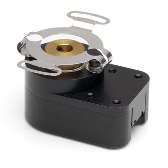
The HB5M is a hollow-shaft/hollow-bore incremental encoder engineered for reliable performance in demanding applications. Its machined aluminum housing, black anodized for protection, accepts shaft diameters from 5 mm to 8 mm and secures directly to the shaft using two set screws.
A flexible anti-rotation bracket allows this hollow shaft encoder to tolerate greater shaft runout than standard kit encoders. The HB5M can accommodate shaft axial play up to ±0.030 in. and shaft runout up to 0.010 in. This hollow shaft encoder is available with a closed cover or with a hole in it for an extended shaft.
The HB5M optical encoder has three available outputs—single-ended, single-ended High-Voltage, and differential, all offered with an optional index channel. For cable runs longer than 10 ft or installations subject to electrical noise, the differential output is recommended for improved signal integrity.
This hollow shaft encoder is designed for use with a secure latching connector. After you make your selections in the Product Configurator, compatible cables and connectors will be displayed below and must be ordered separately.
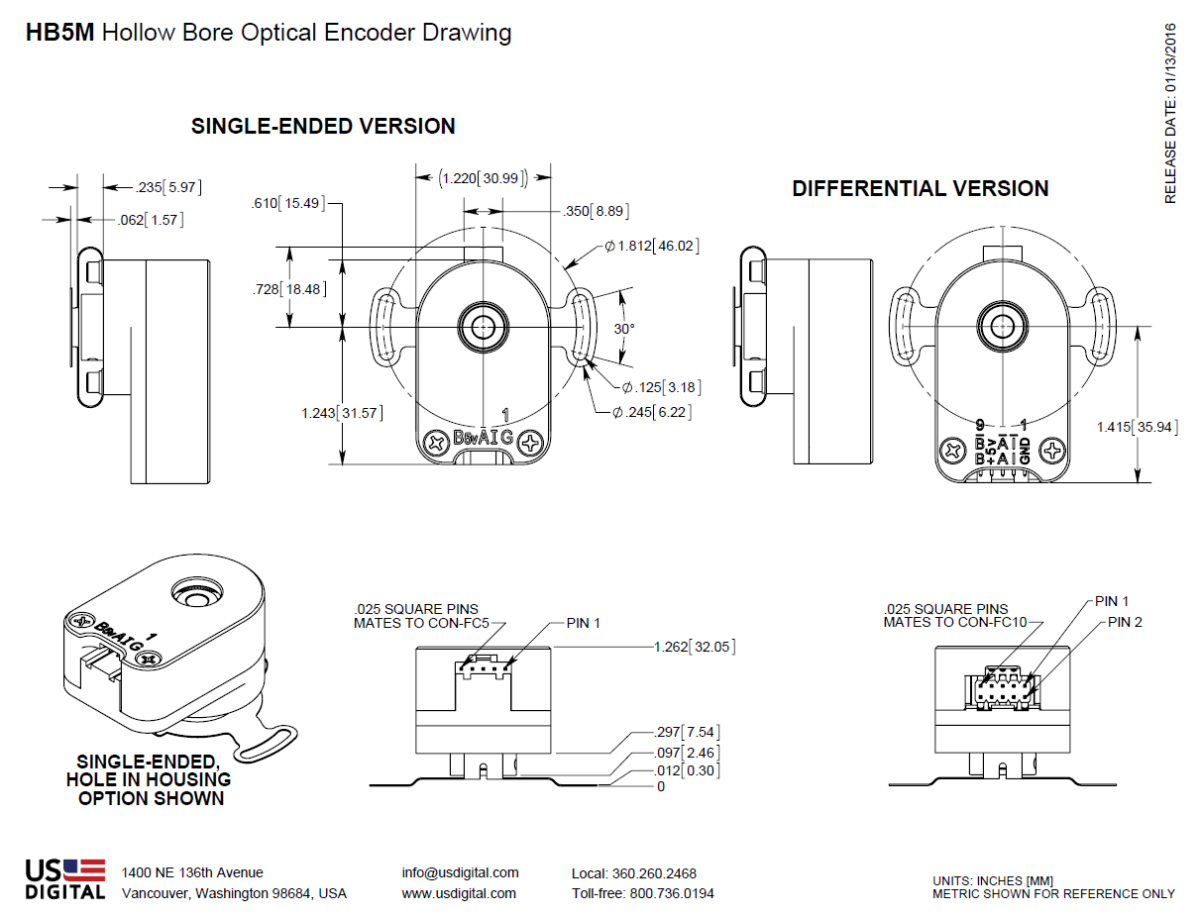
Mechanical Drawings
Specifications
ENVIRONMENTAL
| PARAMETER | VALUE | UNITS |
|---|---|---|
| Operating Temperature, CPR < 2000 | -40 to 100 | C |
| Operating Temperature, CPR ≥ 2000 | -25 to 100 | C |
| Electrostatic Discharge Single-ended (-S version), IEC 61000-4-2 Differential (-D version), Human Body Model High-Voltage, Open-collector (H, C option), IEC 61000-4-2 |
± 4 ± 2 ± 4 |
kV |
| Vibration (10Hz to 2kHz, sinusoidal) | 20 | G |
| Shock (6 milliseconds, half-sine) | 75 | G |
MECHANICAL
| Parameter | Value |
|---|---|
| Max. Acceleration | 100000 rad/sec2 |
| Max. Shaft Speed (mechanical) | 6000 rpm (1) |
| Max. Starting Torque | 0.20 oz-in |
| Max. Bore Load | 2 lb. |
| Weight | 2.84 oz. |
| Max. Shaft Runout | 0.010 in. T.I.R. |
| Max. Shaft Axial Play | ± 0.030 in. |
| Required Shaft Length (From mounting surface) | Min. = 0.3 in. Max. = 1.0 in. with default cover. Max. = No limit with H-option cover. |
| Moment of Inertia | 1.29 x 10^-4 oz-in-sec2 |
| Technical Bulletin TB1001 - Shaft and Bore Tolerances | Download |
(1) The maximum speed due to electrical considerations is dependent on the CPR. See the EM1 and EM2 product pages.
PHASE RELATIONSHIP
A leads B in a clockwise shaft rotation, and B leads A in counterclockwise shaft rotation when viewed from the rear side (opposite flexible mount) of the encoder.
SINGLE-ENDED OPTION
- S option provides 5V TTL compatible outputs
- Specifications apply over the entire operating temperature range
- Typical values are specified at Vcc = 5.0Vdc and 25°C
- For complete details, see the EM1 or EM2 product pages
| PARAMETER | MIN. | TYP. | MAX. | UNITS | CONDITIONS |
|---|---|---|---|---|---|
| Supply Voltage | 4.5 | 5.0 | 5.5 | V | |
| Supply Current | 27 | 33 | mA | CPR < 500, no load | |
| 54 | 62 | mA | CPR ≥ 500 and < 2000, no load | ||
| 72 | 85 | mA | CPR ≥ 2000, no load | ||
| Low-level Output | 0.5 | V | IOL = 8mA max., CPR < 2000 | ||
| 0.5 | V | IOL = 5mA max., CPR ≥ 2000 | |||
| 0.05 | V | no load, CPR < 2000 | |||
| 0.25 | V | no load, CPR ≥ 2000 | |||
| High-level Output | 2.0 | V | IOH = -8mA max. and CPR < 2000 | ||
| 2.0 | V | IOH = -5mA max. and CPR ≥ 2000 | |||
| 4.8 | V | no load and CPR < 2000 | |||
| 3.5 | V | no load and CPR ≥ 2000 | |||
| Output Current Per Channel | -8 | 8 | mA | CPR < 2000 | |
| -5 | 5 | mA | CPR ≥ 2000 | ||
| Output Rise Time | 110 | nS | CPR < 2000 | ||
| 50 | nS | CPR ≥ 2000, ± 5mA load | |||
| Output Fall Time | 100 | nS | CPR < 2000 | ||
| 50 | nS | CPR ≥ 2000, ± 5mA load |
DIFFERENTIAL OPTION
- D Option provides differential line driver output
- Specifications apply over the entire operating temperature range
- Typical values are specified at Vcc = 5.0Vdc and 25°C
- For complete details, see the EM1 or EM2 product pages
| PARAMETER | MIN. | TYP. | MAX. | UNITS | CONDITIONS |
|---|---|---|---|---|---|
| Supply Voltage | 4.5 | 5.0 | 5.5 | V | |
| Supply Current | 29 | 36 | mA | CPR < 500, no load | |
| 56 | 65 | mA | CPR ≥ 500 and < 2000, no load | ||
| 74 | 88 | mA | CPR ≥ 2000, no load | ||
| Low-level Output | 0.2 | 0.4 | V | IOL = 20mA max. | |
| High-level Output | 2.4 | 3.4 | V | IOH = -20mA max. | |
| Differential Output Rise/Fall Time | 15 | nS |
HIGH-VOLTAGE OPTION
- H option uses a higher supply voltage and provides both single-ended and open-collector outputs
- Single-ended outputs are 5V TTL compatible (same as S option). See Pin-out.
- Specifications apply over the entire operating temperature range
- For complete details, see the EM1 or EM2 product pages
| PARAMETER | MIN. | TYP. | MAX. | UNITS | CONDITIONS |
|---|---|---|---|---|---|
| Supply Voltage | 7.5 | 30.0 | V | ||
| Supply Current, 24V power | 8 | 10 | mA | CPR < 500, no load | |
| 16 | 19 | mA | CPR ≥ 500 and < 2000, no load | ||
| 22 | 25 | mA | CPR ≥ 2000, no load | ||
| Open Collector "On" Resistance | 2 | ohms | |||
| Open Collector Sink Current | 200 | mA | |||
| Output Low Voltage | 0.4 | V | 200 mA sink current | ||
| Open Collector Pullup Voltage | 50 | V |
PIN-OUTS
|
5-PIN SINGLE-ENDED |
10-PIN DIFFERENTIAL D OPTION (2) |
||
|---|---|---|---|
| Pin | Description | Pin | Description |
| 1 | Ground | 1 | Ground |
| 2 | Index | 2 | Ground |
| 3 | A channel | 3 | Index- |
| 4 | +5VDC power | 4 | Index+ |
| 5 | B channel | 5 | A- channel |
| 6 | A+ channel | ||
| 7 | +5VDC power | ||
| 8 | +5VDC power | ||
| 9 | B- channel | ||
| 10 | B+ channel | ||
| 10-PIN HIGH-VOLTAGE H OPTION (2) |
|
|---|---|
| Pin | Description |
| 1 | Ground |
| 2 | Ground |
| 3 | Index- (open collector) |
| 4 | Index+ (single-ended) |
| 5 | A- channel (open collector) |
| 6 | A+ channel (single-ended) |
| 7 | 7.5-30V power |
| 8 | 7.5-30V power |
| 9 | B- channel (open collector) |
| 10 | B+ channel (single-ended) |
(1) 5-pin single-ended mating connector is CON-FC5.
(2) 10-pin differential mating connector is CON-FC10.
Notes
- Cables and connectors are not included and must be ordered separately.
- US Digital® warrants its products against defects in materials and workmanship for two years. See complete warranty for details.
- For ordering information please see the Compatible Cables / Connectors section above.
Configuration Options |
||||||||||||||||||||||||||||||||||||||||||||||||
| HB5M | - | CPR (Cycles Per Revolution) 32 50 96 100 120 192 200 250 256 360 400 500 512 540 720 800 900 1000 1024 1250 2000 2048 2500 4000 4096 5000 | - | Bore Size 197 (5.0mm) 236 (6.0mm) 250 (1/4") 313 (5/16") 315 (8.0mm) | - | Index IE (Index) NE (Non-Index) | - | Output S (Single-Ended) H (Single-Ended High-Voltage) D (Differential) | - | Housing D (Default) H (Hole in Cover) | ||||||||||||||||||||||||||||||||||||||
|
PLEASE NOTE: This chart is for informational use only. Certain product configuration combinations are not available. Visit the HB5M product page for pricing and additional information. |
||||||||||||||||||||||||||||||||||||||||||||||||