SEI-USB Features
- USB 1.1 device communicates at 12 Mbit/sec
- Compatible with USB 2.0 hubs and host adapters
- Supports up to 15 total devices on the SEI bus
- Supports SEI bus lengths up to 1,000 feet, depending on the number of devices attached.
- USB port on the PC provides power for the SEI-USB and SEI bus devices (120mA max using USB port power).
- Short-circuit power protection between the USB port and the SEI bus.
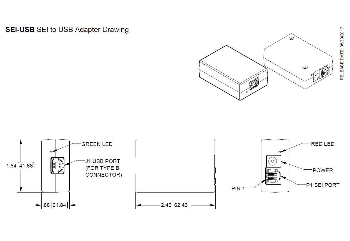
- Includes two LED indicators: green for USB power-sense and red to indicate additional external power is required.
Material Compliance Statement: This product does NOT contain banned levels of substances as defined in European Directive 2011/65/EU. Specifically, Lead (Pb), Mercury (Hg), Cadmium (Cd), Hexavalent Chromium (CR+6), Poly Brominated Biphenyls (PBB), and Poly Brominated Diphenyl Ethers (PBDE) are not found above the threshold level given in the 2011/65/EU Directive.
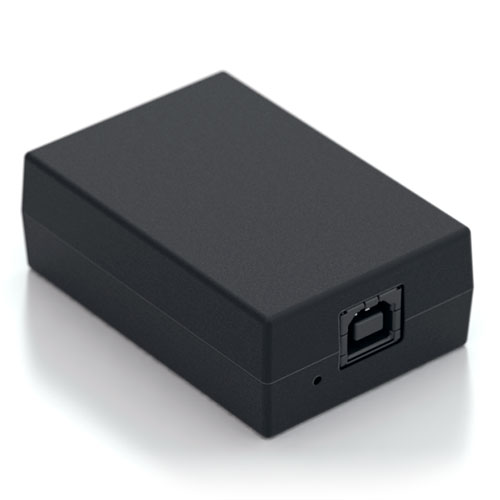
SEI-USB Product Description
The SEI-USB is an interface module that connects US Digital's SEI compatible devices to a standard USB 1.1 / 2.0 port.
The SEI (Serial Encoder Interface) bus is a network that connects up to 15 addressable SEI devices using a single 6-wire telephone-type cable up to 1000 feet long. The SEI bus uses two differential signaling pairs, one for busy flow control and the other for bi-directional serial data.
The SEI-USB will supply power from the USB port to several SEI devices on the bus (for example, five A2 encoders at a distance of 250 feet). The SEI-USB limits the power to the maximum design spec of the USB port. A red LED next to the SEI connector will be lit when additional power is required, and you should then use the included PS-12 power supply. A green LED next to the USB connector is lit when the USB connection is established with the host.
Mechanical Drawings
Specifications
ENVIRONMENTAL
| PARAMETER | MIN. | TYP. | MAX. | UNITS |
|---|---|---|---|---|
| Operating Temperature | 0 | 70 | C | |
| Electrostatic Discharge, USB pins | ± 15 | kV Human Body Model |
ELECTRICAL
| PARAMETER | MIN. | TYP. | MAX. | UNITS | PORT / PIN | NOTES |
|---|---|---|---|---|---|---|
| External Supply Voltage (optional) | 8.5 | 12 | 16.0 | V | J3 | The external supply is used when the USB port power (J1) is not adequate to provide sufficient power when a large number of SEI devices are connected to the SEI-USB. |
| External Supply Current (optional) | - | - | 1500 | mA | J3 | - |
| SEI-USB PWR Pin Voltage | 8.0 | 9.5 | 10.5 | V | P1 / 4 | Generated by the SEI-USB using the USB port power (J1). Assumes that the USB PWR pin is not in a current limit mode as indicated by the red power-fault LED. |
| SEI-USB PWR Pin Current | - | - | 120 | mA | P1 / 4 | Adequate to directly power five A2 encoders at a distance of 250 feet. |
| USB Port PWR Current, No Devices | <0.5 | 17 | 20 | mA | J1 / 1 | SEI-USB device load only, no devices attached. |
| USB Port PWR Current, 5 A2 Devices | - | 275 | 480 | mA | - | With 5 A2 devices attached. |
| Differential SEI Output Voltage | 2.0 | 3.2 | 5.0 | V | P1 / 5, 6 | - |
| Differential SEI Input Voltage | 0.2 | - | 5.0 | V | P1 / 2, 3 and P1 / 5, 6 | - |
| Common-mode SEI Output Voltage | 2.0 | 2.5 | 3.0 | V | P1 / 5, 6 | - |
| Common-mode SEI Input Voltage | -4.5 | - | 3.0 | V | P1 / 2, 3 and P1 / 5, 6 | - |
| SEI Input Current (In=0-5V) | -15 | - | 15 | mA | P1 / 2, 3 and P1 / 5, 6 |
TIMING
| PARAMETER | MIN. | TYP. | MAX. | UNITS | PORT / PIN | NOTES |
|---|---|---|---|---|---|---|
| Data Rate | 1.2 | - | 115.2 | kBaud | P1 / 5, 6 | Virtual COM port speed. |
Data Latency: The USB data latency timer is preset to a default value of 16ms by the driver manufacturer. This means that data could be sitting in the FIFO buffer up to 16ms before it is forced to transmit. If Windows is allowed to search the internet for the device drivers when the "Found New Hardware" wizard is displayed, then the latency timer will be set to 16ms. The latency timer can be set to a minimum of 1ms using USBSpeedBoost software found on the US Digital website.
PIN-OUTS
SEI Port (P1)
| PIN | NAME | DESCRIPTION |
|---|---|---|
| 1 | GND | Ground, common for power, data and busy pairs |
| 2 | Busy+ | Differential input line, active high, has 330 Ω pull down |
| 3 | Busy- | Differential input line, active low, has 330 Ω pull up |
| 4 | PWR | Power supply output to encoder bus (USB or external) |
| 5 | Data L | Bidirectional differential data line, has 330 Ω pull up |
| 6 | Data H | Bidirectional differential data line, has 330 Ω pull down |
INCLUDED ACCESSORIES
Notes
- US Digital® warrants its products against defects in materials and workmanship for two years. See complete warranty for details.
Configuration Options |
||||
| SEI-USB | - | Power Supply With Power Supply N (Without Power Supply) | ||
|
PLEASE NOTE: This chart is for informational use only. Certain product configuration combinations are not available. Visit the SEI-USB product page for pricing and additional information. |
||||