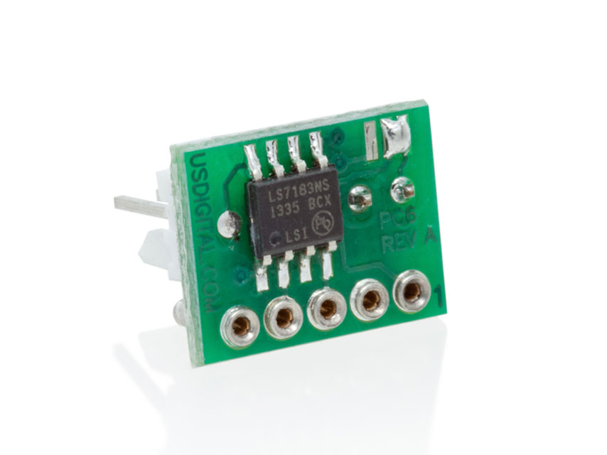
PC6-X-X-X INPUT PIN-OUT
| PIN |
NAME |
DESCRIPTION |
| 1 |
GND |
Ground |
| 2 |
I |
Index |
| 3 |
A |
A channel |
| 4 |
VCC |
+5 VCC |
| 5 |
B |
B channel |
PC6-U-X-X OUTPUT PIN-OUT. UP COUNT / DOWN COUNT (LFLS7183)
| PIN |
NAME |
DESCRIPTION |
| 1 |
GND |
Ground |
| 2 |
I |
Index |
| 3 |
/DNCK |
Down clock |
| 4 |
VCC |
+5 VCC |
| 5 |
/UPCK |
Up clock |
PC6-C-X-X OUTPUT PIN-OUT. CLOCK, UP/DN (LFLS7184)
| PIN |
NAME |
DESCRIPTION |
| 1 |
GND |
Ground |
| 2 |
I |
Index |
| 3 |
UP/DN |
Up/Down |
| 4 |
VCC |
+5 VCC |
| 5 |
/CLK |
Clock output |
Index (Pin 2)
The index signal is routed unchanged, directly from the encoder.
PC6-U-x, pin 3 (LFLS7183).
Normally high, low-true. Down counts are enabled only when B leads A (clockwise rotation). One pulse is generated per encoder cycle using the PC6-U-1 and four pulses are generated using the PC6-U-4. For example, a 500 CPR encoder will produce five hundred clocks/rev. using the PC6-U-1 and 2000 clocks/rev. using the PC6-U-4. The external counter should count on the rising (high-going) edge of this output.
PC6-U-x, pin 5 (LFLS7183).
Normally high, low-true. Up counts are enabled only when A leads B (counterclockwise rotation). One pulse is generated per encoder cycle using the PC6-U-1 and four pulses are generated using the PC6-U-4. For example, a 500 CPR encoder will produce 500 clocks/rev. using the PC6-U-1 and 2000 clocks/rev. using the PC6-U-4. The external counter should count on the rising (high-going) edge of this output.
PC6-C-x, pin 3 (LFLS7184)
This output steers the external counter up or down. High = Up (A leads B), Low = Down (B leads A).
PC6-C-x, pin 5 (LFLS7184)
Normally high, low-true. One pulse is generated per encoder cycle using the PC6-C-1 and four pulses are generated using the PC6-C-4. For example, a 500 CPR encoder will produce 500 clocks/rev. using the PC6-C-1 and 2000 clocks/rev. using the PC6-C-4. The external counter should count on the rising (high-going) edge of this output.
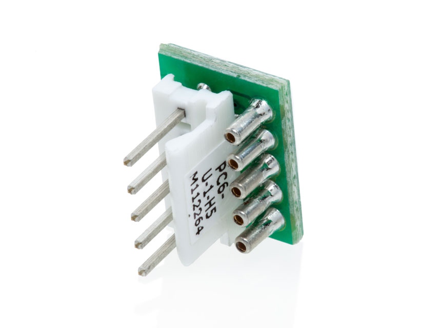
Connector
The output connector on the PC6 is TE#640456-5.