The EADAPT is no longer available for purchase.
EADAPT Product Description
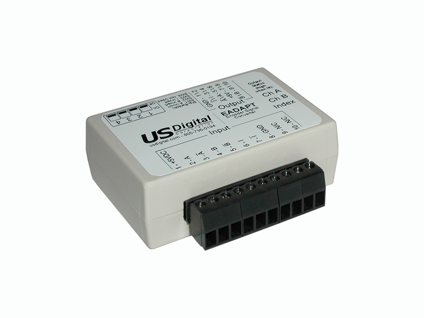
The EADAPT is an inline encoder signal converter that allows the user to invert or not invert any A, B, and Index encoder signals. The EADAPT can use this to invert the encoder's rotation sense. The input quadrature signals can be single-ended or differential. Single-ended inputs can have amplitudes up to 30V. In addition, the index can be optionally gated by both the A/B channels going low to get an index pulse that is at most one quadrature statewide. This feature is useful when using encoders with a wide index pulse that spans multiple quadrature states.
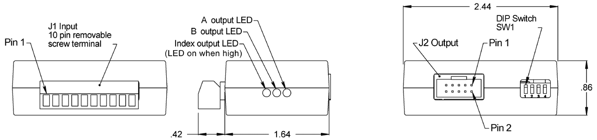
Encoder input signals enter through a 10-position pluggable screw terminal block. Single-ended encoders should be placed close (less than 2 ft. preferably) to the EADAPT on the input side to limit noise. The EADAPT output is made through a 10-pin latching connector compatible with US Digital encoder interface products. The +5VDC supply voltage for the EADAPT is supplied from the J2 output connector. Three LEDs indicate when the associated A, B, or Index outputs are high.
Product Specifications
View here or download the specifications
OPERATING CONDITIONS
| PARAMETER |
MIN. |
TYP. |
MAX. |
UNITS |
| Supply Voltage |
4.75 |
5.0 |
5.25 |
V |
| Supply Current (no output load, LEDs off) |
|
30 |
|
mA |
| Storage Temperature |
-40 |
|
100 |
C |
| Operating Temperature |
0 |
|
70 |
C |
| Humidity (non-condensing) |
0 |
|
95 |
% |
- For typical input voltage thresholds and output voltage levels, refer to the 26C31 and 26C32 IC datasheets.
DIP SWITCH SETTINGS
| SWITCH |
DESCRIPTION |
| 1 |
A channel polarity:
switch down = non-invert
switch up = invert |
| 2 |
B channel polarity:
switch down = non-invert
switch up = invert |
| 3 |
Index channel polarity:
switch down = non-invert
switch up = invert |
| 4 |
no function |
PIN-OUTS
J1 Input (Screw Terminal):
| PIN |
DESCRIPTION |
| 1 |
+5V power (direct connection to J2 pins 7,8) |
| 2 |
A+ channel |
| 3 |
A- channel |
| 4 |
B+ channel |
| 5 |
B- channel |
| 6 |
Index+ |
| 7 |
Index- |
| 8 |
Ground |
| 9 |
N/C |
| 10 |
N/C |
J2 Output (10-pin latching):
| PIN |
DESCRIPTION |
| 1 |
Ground |
| 2 |
Ground |
| 3 |
Index- |
| 4 |
Index+ |
| 5 |
A- channel |
| 6 |
A+ channel |
| 7 |
+5V power |
| 8 |
+5V power |
| 9 |
B- channel |
| 10 |
B+ channel |
PRODUCT CHANGE NOTIFICATIONS
| Title |
Date |
Description |
Download |
| PCN 1011 |
9/21/2011 |
The AD2B, AD4B, AD7, EADAPT, EDAC2, EDIVIDE, EPOT, EQUAD, ESUM, ESWITCH, ETACH2, SEI-USB, USB-232 currently utilizes a printed thermal transfer label. This label will no longer be used and will be replaced by laser marking directly onto the housing of the product. The purpose for this change is to create a more durable solution, and eliminate the possibility of the label being inadvertently removed from the housing. |
Download |
Additional Information
Product Notes
-
Cables and connectors are not included and must be ordered separately.
-
US Digital® warrants its products against defects in materials and workmanship for two years. See complete warranty for details.
Datasheets
Feedback
US Digital's mission is a commitment to quality and constant improvement. If you find an error to a product on this page, please let us know!