HB6M Product Description

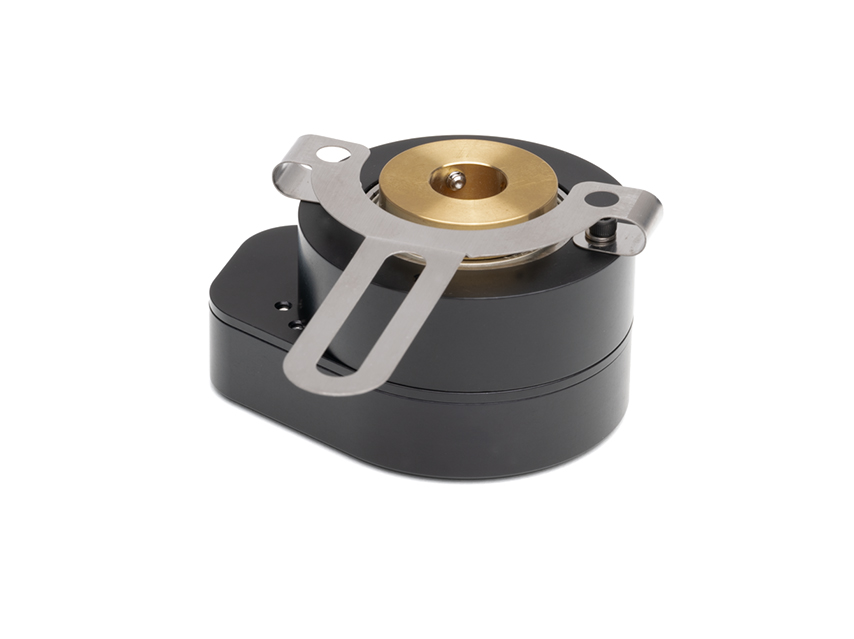
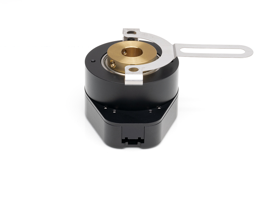
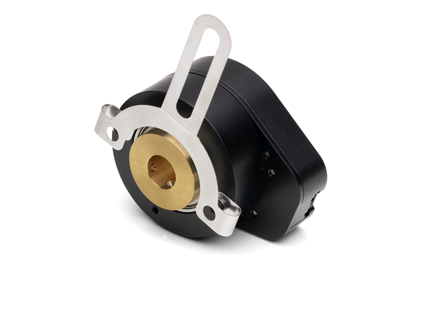
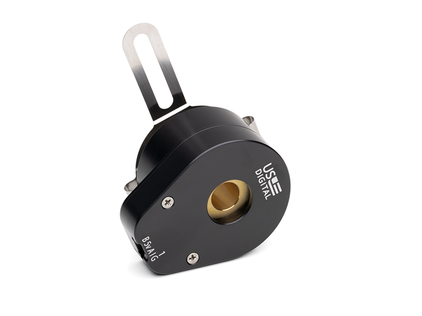
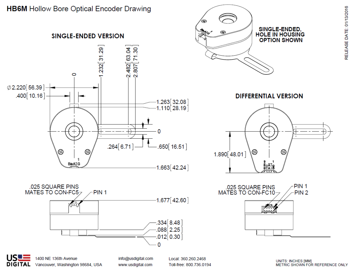
The HB6M is a high-resolution hollow bore (hollow shaft/thru-bore) optical encoder with a machined aluminum enclosure and an anodized protective finish. The HB6M optical incremental encoder is designed to easily mount to an existing shaft to provide digital feedback information. Typical applications include motor feedback, process control, robotics, textile machines, and elevator controls.
The HB6M bearing style encoder features a hollow bore that accepts shaft diameters from 0.236 in. to 0.750 in. in diameter. The encoder slips over the shaft and is locked into place with two 6-32 set screws. A flexible anti-rotation mount makes the encoder more tolerant of shaft runout than a standard kit encoder. The HB5M can accommodate shaft axial play up to ±0.030 in. and shaft runout up to 0.010 in. The flexible tether provides single-point mounting for bolt circle diameters from 2.5 in. to 5.0 in.
The HB6M housing comes standard with a closed cover or an optional hole in the body to allow a shaft to pass completely through the encoder.
A secure connection to the HB6M Series encoder is made through a 5-pin (single-ended versions) or 10-pin (differential, high-voltage or open-collector versions) latching connector. The mating connectors are available from US Digital with several cable options and lengths.
Product Specifications
View here or download the specifications
ENVIRONMENTAL
| PARAMETER |
VALUE |
UNITS |
| Operating Temperature (CPR < 3600) |
-40 to 100 |
C |
| Operating Temperature (CPR ≥ 3600) |
-25 to 100 |
C |
Electrostatic Discharge
Single-ended (-S version), IEC 61000-4-2
Differential (-D version), Human Body Model
High-Voltage, Open-collector (H, C option), IEC 61000-4-2 |
± 4
± 2
± 4 |
kV |
| Vibration (10Hz to 2kHz, sinusoidal) |
20 |
G |
| Shock (6 milliseconds, half-sine) |
75 |
G |
MECHANICAL
| PARAMETER |
DIMENSION |
| Max. Acceleration |
100000 rad/sec² |
| Max. Shaft Speed |
6000 rpm |
| Max. Starting Torque |
0.70 oz-in |
| Max. Bore Loading |
5 lb. |
| Weight |
11.5 oz. |
| Max. Shaft Runout |
0.010 in. T.I.R. |
| Max. Shaft Axial Play |
± 0.030 in. |
| Required Shaft Length (From mounting surface) |
Min. = 0.3 in.
Max. = 1.4 in. with default cover.
Max. = No limit with H-option cover. |
| Moment of Inertia |
3.7x10^-3 oz-in-sec² |
| Technical Bulletin TB1001 - Shaft and Bore Tolerances |
Download |
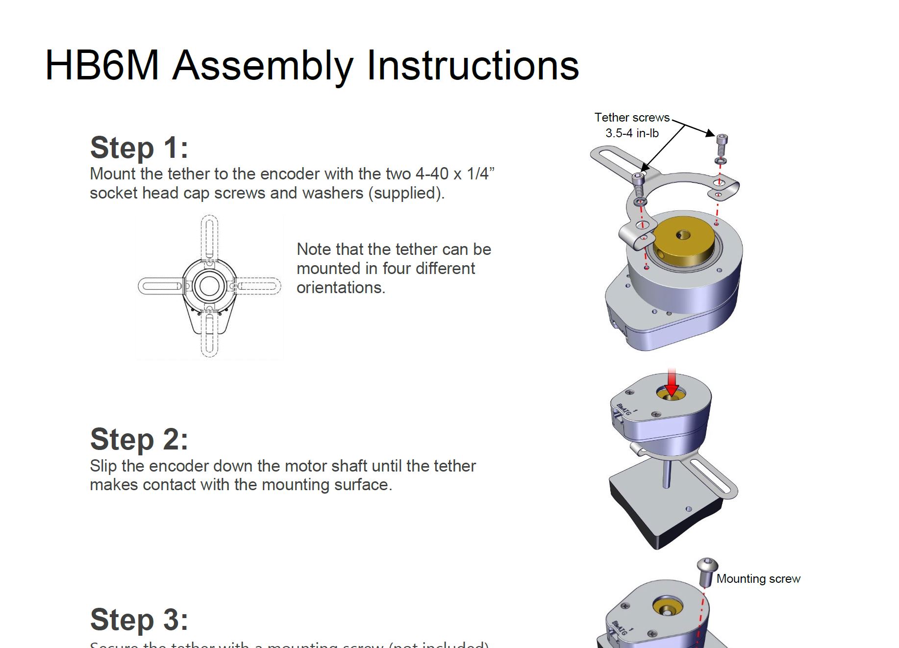
TETHER MOUNTING
The tether is shipped detached and may be mounted in the four different methods as shown below.

PHASE RELATIONSHIP
A leads B in a clockwise shaft rotation, and B leads A in counterclockwise shaft rotation viewed from the rear side (opposite flexible mount) of the encoder.
SINGLE-ENDED OPTION
- S option provides 5V TTL compatible outputs
- Specifications apply over the entire operating temperature range
- Typical values are specified at Vcc = 5.0Vdc and 25°C
- For complete details, see the EM1 and EM2 product pages
| PARAMETER |
MIN. |
TYP. |
MAX. |
UNITS |
CONDITIONS |
| Supply Voltage |
4.5 |
5.0 |
5.5 |
V |
|
| Supply Current |
|
27 |
33 |
mA |
CPR < 1000, no load |
| |
54 |
62 |
mA |
CPR ≥ 1000 and < 3600, no load |
| |
72 |
85 |
mA |
CPR ≥ 3600, no load |
| Low-level Output |
|
|
0.5 |
V |
IOL = 8mA max., CPR < 3600 |
| |
|
0.5 |
V |
IOL = 5mA max., CPR ≥ 3600 |
| |
0.05 |
|
V |
no load, CPR < 3600 |
| |
0.25 |
|
V |
no load, CPR ≥ 3600 |
| High-level Output |
2.0 |
|
|
V |
IOH = -8mA max., CPR < 3600 |
| 2.0 |
|
|
V |
IOH = -5mA max., CPR ≥ 3600 |
| |
4.8 |
|
V |
no load, CPR < 3600 |
| |
3.5 |
|
V |
no load, CPR ≥ 3600 |
| Output Current Per Channel |
-8 |
|
8 |
mA |
CPR < 3600 |
| -5 |
|
5 |
mA |
CPR ≥ 3600 |
| Output Rise Time |
|
110 |
|
nS |
CPR < 3600 |
| |
50 |
|
nS |
CPR ≥ 3600 |
| Output Fall Time |
|
35 |
|
nS |
CPR < 3600 |
| |
50 |
|
nS |
CPR ≥ 3600 |
DIFFERENTIAL OPTION
- D Option provides differential line driver output
- Specifications apply over the entire operating temperature range
- Typical values are specified at Vcc = 5.0Vdc and 25°C
- For complete details, see the EM1 and EM2 product pages
| PARAMETER |
MIN. |
TYP. |
MAX. |
UNITS |
CONDITIONS |
| Supply Voltage |
4.5 |
5.0 |
5.5 |
V |
| Supply Current |
|
29 |
36 |
mA |
CPR < 1000, no load |
| |
56 |
65 |
mA |
CPR ≥ 1000 and < 3600, no load |
| |
74 |
88 |
mA |
CPR ≥ 3600, no load |
| Low-level Output |
|
0.2 |
0.4 |
V |
IOL = 20mA max. |
| High-level Output |
2.4 |
3.4 |
|
V |
IOH = -20mA max. |
| Differential Output Rise/Fall Time |
|
|
15 |
nS |
|
HIGH-VOLTAGE OPTION
- H option uses a higher supply voltage and provides both single-ended and open-collector outputs
- Single-ended outputs are 5V TTL compatible (same as S option)
- Specifications apply over the entire operating temperature range
- For complete details, see the EM1 or EM2 product pages
| PARAMETER |
MIN. |
TYP. |
MAX. |
UNITS |
CONDITIONS |
| Supply Voltage |
7.5 |
|
30.0 |
V |
|
| Supply Current, 24V power |
|
8 |
10 |
mA |
CPR < 500, no load |
| |
16 |
19 |
mA |
CPR ≥ 500 and < 2000, no load |
| |
22 |
25 |
mA |
CPR ≥ 2000, no load |
| Open Collector "On" Resistance |
|
2 |
|
ohms |
|
| Open Collector Sink Current |
|
|
200 |
mA |
|
| Output Low Voltage |
|
|
0.4 |
V |
200 mA sink current |
| Open Collector Pullup Voltage |
|
|
50 |
V |
|
PIN-OUTS
|
5-PIN SINGLE-ENDED
S OPTION (1)
|
10-PIN DIFFERENTIAL
D OPTION (2) |
| Pin |
Description |
Pin |
Description |
| 1 |
Ground |
1 |
Ground |
| 2 |
Index |
2 |
Ground |
| 3 |
A channel |
3 |
Index- |
| 4 |
+5VDC power |
4 |
Index+ |
| 5 |
B channel |
5 |
A- channel |
| |
|
6 |
A+ channel |
| |
|
7 |
+5VDC power |
| |
|
8 |
+5VDC power |
| |
|
9 |
B- channel |
| |
|
10 |
B+ channel |
10-PIN HIGH-VOLTAGE
H OPTION (2) |
| Pin |
Description |
| 1 |
Ground |
| 2 |
Ground |
| 3 |
Index- (open collector) |
| 4 |
Index+ (single-ended) |
| 5 |
A- channel (open collector) |
| 6 |
A+ channel (single-ended) |
| 7 |
7.5-30V power |
| 8 |
7.5-30V power |
| 9 |
B- channel (open collector) |
| 10 |
B+ channel (single-ended) |
(1) 5-pin single-ended mating connector is CON-FC5.
(2) 10-pin differential mating connector is CON-FC10.
PRODUCT CHANGE NOTIFICATIONS
| Title |
Date |
Description |
Download |
| HB5M, HB6M & HD25 - PCN 7315 |
5/17/2023 |
As part of our ongoing continuous improvement efforts, we are updating our HB5M, HB6M and HD25 series of optical encoders to make product labeling clearer and permanent. The aluminum housing of these encoders will now be anodized black, and labeling will be laser etched onto the surface, providing more contrast and legibility. Previously pin-outs were machined into the housing and product labeling was printed onto an adhesive label that was placed on the side of the product. Product labeling will also now appear on the top surface of the encoder near the pin-out labeling. |
Download |
| EM1 LED Die - PCN 1016 |
2/7/2013 |
As part of US Digital's continual assurance of supply strategy, we have qualified additional sources for our LED die used in our EM1 encoder module, which in turn impacts all of the following products:
EM1, E2, E3, E5, E6, H1, H15, H3, H5, H6, HB5M, HB6M, HD25, PE, S1, S2, S5, S6, T5 and T6
The device specification will remain the same, i.e. there will be no change to form, fit or function of the product(s) as specified by US Digital. The appropriate quality and reliability testing has been performed on representative products to ensure normal parametric distribution, consistent with US Digital's quality and reliability standards. |
Download |
| EM1 & EM2 Update - PCN 4199 |
1/14/2014 |
Based on our continuous process improvement program, US Digital is changing the current marking method for our EM1 and EM2 encoder modules to a serialization method. This change will allow for each module to have a unique code; the current marking method is based on a date code system that includes all encoder modules produced within a specific week / year. The serialization system will be based on a hexadecimal system. |
Download |
Additional Information
Product Notes
-
Cables and connectors are not included and must be ordered separately.
-
US Digital® warrants its products against defects in materials and workmanship for two years. See complete warranty for details.
Datasheets
Assembly Instructions
Related
3D Model Downloads
Please
configure your product first
to download a 3D model.
(Note: The formats below will become links if there are 3D models available.)
-
SolidWorks Format
-
IGES Format
-
Parasolid Format
-
STEP Format
Product Configurator
Our products are not currently available for direct online purchase. To place an order please contact us directly with your part number.
For purchasing or volume discounts, please configure the part above, then use the completed part number and contact us!
Feedback
US Digital's mission is a commitment to quality and constant improvement. If you find an error to a product on this page, please let us know!