The PE is no longer available for purchase.
PE Product Description
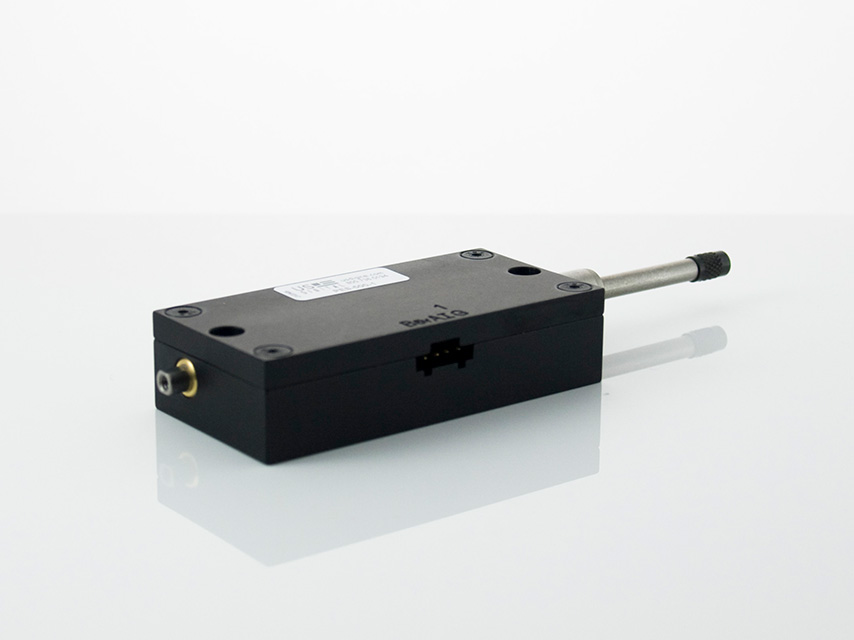
The PE series linear plunger-style optical encoder has a machined aluminum enclosure. The PE provides either single-ended or differential quadrature encoder output in a convenient mechanical package. Various CPI (counts per inch) ranging from 120 CPI to 2000 CPI are available. Using x4 quadrature counting, the available resolutions range from 0.00013 in. to 0.0021 in. Note that 127 CPI gives a resolution of 50 micrometers.
The PE features smooth linear bearings for repeatable measurements and an internal spring to return the plunger to its fully extended position. Standard linear measurement ranges are from 1 to 2 inches. The precision plunger has #4-48 threads on both ends to accept industry-standard contact points. The PE may be mounted four different ways: the #4-40 clearance body through holes, the #4-40 tapped blind holes, the standard 3/8 in. diameter mounting stem, or the lug back option.
The single-ended output interface is normally designed for applications of 10 feet or less. For longer cable lengths, the differential output interface is recommended.
The internal encoder module incorporates a lensed LED light source and a monolithic photodetector array. The monolithic photodetector has signal shaping electronics that produce a two-channel quadrature with optional index bounceless TTL output. When Index is specified, the default location is in the middle of the linear probe's range of travel with a location tolerance of ±0.050 in.
For differential versions: the internal differential line driver (26C31) can source and sink 20mA at TTL levels. The recommended receiver is industry standard 26C32. Maximum noise immunity is achieved when the differential receiver is terminated with a 150 Ω resistor in series with a .0047 μF capacitor placed across each differential pair. The capacitor simply conserves power; otherwise, power consumption would increase by approximately 20 mA per pair or 40 mA for 2 pairs.
A secure connection to the PE encoder is made through a 5-pin (single-ended versions) or 10-pin (differential versions) polarized connector (sold separately). The mating connectors are available from US Digital with several cable options and lengths.
Product Specifications
View here or download the specifications
ENVIRONMENTAL
The PE performs best over a 0 C to 50 C temperature range due to a fairly linear temperature coefficient. They will however, operate at temperatures above 50C, but the thermal temperature coefficient becomes non linear at elevated temperatures. The negative temperature coefficient indicates the actual measured distance will decrease slightly with temperature increase.
| PARAMETER |
SPECIFICATION |
| Recommended Operating Temperature |
0 C to 50 C |
| 1" Product Temperature Coefficient |
-0.000036 in/C |
| 2" Product Temperature Coefficient |
-0.000075 in/C |
| Operating Temperature, CPI < 1000 |
-40 to 100 C |
| Operating Temperature, CPI ≥ 1000 |
-25 to 100 C |
| Vibration (5 Hz to 2000 Hz) |
20 G |
| Electrostatic Discharge |
± 4 kV Human Body Model |
MECHANICAL
| PARAMETER |
DIMENSION |
UNITS |
| Plunger Force (1" version) |
3 to 6 typical |
oz. |
| Plunger Force (2" version) |
3 to 9 typical |
oz. |
| Travel (1" version) |
1.050 min. |
in. |
| Travel (2" version) |
2.050 min. |
in. |
| Side Load |
1 |
lb. |
- When Index is specified, the default location is in the middle of the linear probe's range of travel with a location tolerance of ±0.050".
PHASE RELATIONSHIP
A leads B for inward plunger motion, and B leads A for outward plunger motion (see the EM1 or EM2 pages).
TRACKING SPEED
The maximum tracking speed of the encoder can be calculated as follows:
Maximum tracking speed ( in. / sec.) = 300000/CPI. Where CPI is the counts-per-inch of the encoder.
The tracking speed for several common CPI's are shown in the table below.
| PARAMETER |
MAX. |
UNITS |
| Tracking Speed, 125 CPI |
800 |
in/sec |
| Tracking Speed, 127 CPI |
787 |
in/sec |
| Tracking Speed, 250 CPI |
400 |
in/sec |
| Tracking Speed, 500 CPI |
200 |
in/sec |
| Tracking Speed, 1000 CPI |
360 |
in/sec |
| Tracking Speed, 2000 CPI |
360 |
in/sec |
RESOLUTIONS
The position resolution in inches using x4 quadrature counting (count every transition of the A and B outputs) can be calculated as follows:
Resolution = 1/(4*CPI) where CPI is the counts-per-inch of the encoder. Several common values are shown in the table below.
| CPI |
RESOLUTION |
| 125 |
0.002 in. |
| 127 |
50.0 μm |
| 250 |
0.0010 in. |
| 500 |
0.0005 in. |
| 1000 |
0.00025 in. |
| 2000 |
0.000125 in. |
Other resolutions may be available upon request.
SINGLE-ENDED ELECTRICAL
- Specifications apply over entire operating temperature range.
- Typical values are specified at Vcc = 5.0Vdc and 25°C.
- For complete details, see the EM1 or EM2 product pages.
| PARAMETER |
MIN. |
TYP. |
MAX. |
UNITS |
CONDITIONS |
| Supply Voltage |
4.5 |
5.0 |
5.5 |
V |
|
| Supply Current |
|
27 |
33 |
mA |
CPI < 300, no load |
| |
55 |
62 |
mA |
CPI ≥ 300, no load |
| Low-level Output |
|
|
0.5 |
V |
IOL = 8mA max. |
| High-level Output |
2.0 |
|
|
V |
IOH = -8mA max. |
| 4.2 |
4.8 |
|
V |
no load |
| Output Current Per Channel |
-8 |
|
8 |
mA |
|
| Output Rise Time |
|
110 |
|
nS |
|
| Output Fall Time |
|
35 |
|
nS |
|
DIFFERENTIAL ELECTRICAL
- Specifications apply over entire operating temperature range.
- Typical values are specified at Vcc = 5.0Vdc and 25°C.
- For complete details, see the EM1 product page.
| PARAMETER |
MIN. |
TYP. |
MAX. |
UNITS |
CONDITIONS |
| Supply Voltage |
4.5 |
5.0 |
5.5 |
V |
| Supply Current |
|
29 |
36 |
mA |
CPI < 300, no load |
| |
57 |
65 |
mA |
CPI ≥ 300, no load |
| Low-level Output |
|
0.2 |
0.4 |
V |
IOL = 20mA max. |
| High-level Output |
2.4 |
3.4 |
|
V |
IOH = -20mA max. |
| Differential Output Rise/Fall Time |
|
|
15 |
nS |
|
PIN-OUT
5-PIN SINGLE-ENDED:
| PIN |
DESCRIPTION |
| 1 |
Ground |
| 2 |
Index |
| 3 |
A channel |
| 4 |
+5VDC power |
| 5 |
B channel |
10-PIN DIFFERENTIAL:
| PIN |
DESCRIPTION |
| 1 |
Ground |
| 2 |
Ground |
| 3 |
Index- |
| 4 |
Index+ |
| 5 |
A- channel |
| 6 |
A+ channel |
| 7 |
+5VDC power |
| 8 |
+5VDC power |
| 9 |
B- channel |
| 10 |
B+ channel |
ACCESSORIES
1. For tapped blind hole mounting:
Part #: SCREW-440-250-PH
Description: #4-40 x 1/4"
Quantity Required for Mounting: 4 per encoder
Part #: SCREW-440-375-PH
Description: #4-40 x 3/8"
Quantity Required for Mounting: 4 per encoder
Part #: SCREW-440-500-PH
Description: #4-40 x 1/2"
Quantity Required for Mounting: 4 per encoder
Part #: SCREW-440-625-PH
Description: #4-40 x 5/8"
Quantity Required for Mounting: 4 per encoder
2. For body through hole mounting:
Part #: SCREW-440-1000-PH
Description: #4-40 x 1"
Quantity Required for Mounting: 2 per encoder
PRODUCT CHANGE NOTIFICATIONS
| Title |
Date |
Description |
Download |
| EOL - PE (Linear Probe Encoder) - PCN 5254 |
4/28/2015 |
This PCN is a formal notification that US Digital is discontinuing the PE. |
Download |
| PCN 4464 - CE - RoHS |
6/30/2014 |
US Digital is aware of the increasing attention to world-wide environmental regulations, specifically with regard to the need for hazardous substance restrictions in electronic components and systems. As of July 10th, 2014 US Digital will now be CE Marking certain products inline with compliance under RoHS Directive (2011/65/EU). In order to achieve RoHS Compliance, the products will not contain more than the acceptable levels of the listed restricted substances within the RoHS 2011/65/EU directive.
Part Numbers Affected:
- ED3
- USB4
- QSB
- SEI-USB
- MD2S
- PS-5, PS-12, PS-24, PS-48 (Power Supplies)
- PE
For the part numbers listed above, US Digital cannot confirm that they meet Low-Voltage and EMC Directives and for that reason US Digital cannot support shipping those products / product families into the CE required countries (For Example countries in the EU). Those products can still be shipped to Non-CE required countries with a Statement of Material Conformance to the RoHS Directive 2011/65/EU, in place of a RoHS Compliance Declaration.
|
Download |
| EM1 & EM2 Update - PCN 4199 |
1/14/2014 |
Based on our continuous process improvement program, US Digital is changing the current marking method for our EM1 and EM2 encoder modules to a serialization method. This change will allow for each module to have a unique code; the current marking method is based on a date code system that includes all encoder modules produced within a specific week / year. The serialization system will be based on a hexadecimal system. |
Download |
| EM1 LED Die - PCN 1016 |
2/7/2013 |
As part of US Digital's continual assurance of supply strategy, we have qualified additional sources for our LED die used in our EM1 encoder module, which in turn impacts all of the following products:
EM1, E2, E3, E5, E6, H1, H15, H3, H5, H6, HB5M, HB6M, HD25, PE, S1, S2, S5, S6, T5 and T6
The device specification will remain the same, i.e. there will be no change to form, fit or function of the product(s) as specified by US Digital. The appropriate quality and reliability testing has been performed on representative products to ensure normal parametric distribution, consistent with US Digital's quality and reliability standards. |
Download |
Additional Information
Product Notes
-
Cables and connectors are not included and must be ordered separately.
-
For ordering information please see the Compatible Cables / Connectors section above.
-
US Digital® warrants its products against defects in materials and workmanship for two years. See complete warranty for details.
Datasheets
Feedback
US Digital's mission is a commitment to quality and constant improvement. If you find an error to a product on this page, please let us know!