M3K Features
- Available in incremental and incremental/absolute configurations
- Push-on hub spring loaded collet design
- Motor shaft length of 0.500 in. or 0.390 in.
- Fits shaft diameters from 3mm to 0.250 in.
- 1 to 8,192 cycles per revolution (CPR)
- 4 to 32,768 pulses per revolution (PPR)
- A/B/Index incremental output and 12-bit PWM output for absolute position
- Latching connector
- Single 4~16V supply
- 5V logic level outputs
M3K Product Description
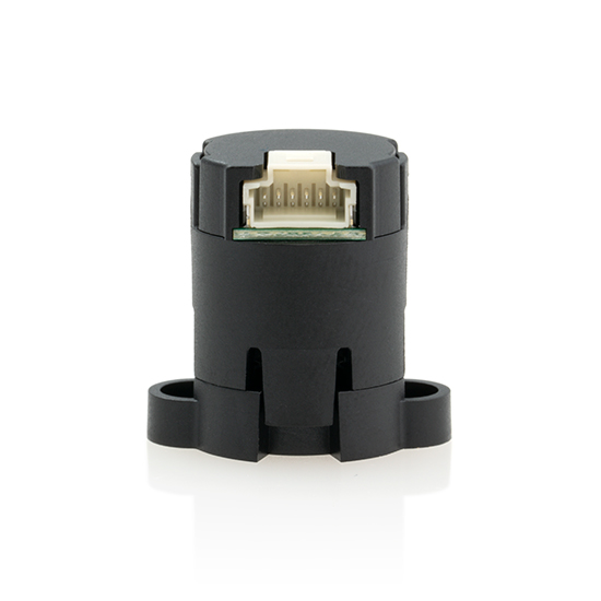
The M3K miniature magnetic kit encoder is designed to provide shaft position feedback for high volume, restricted space applications. The M3K outputs A, B, and Index digital quadrature signals and optional pulse width modulated (PWM) absolute position. The PWM output provides a pulse width duty cycle that is proportional to the absolute shaft position.
The M3K features a push-on hub design that can easily mount from 3mm to 0.250 in. diameter shafts. The M3K consists of three components: base, push-on magnetic hub, and encoder body. Various base options accommodate different length shafts, including a 0.586 in. or 0.750 in. bolt circle. No tools are required to install the push-on, collet-gripping hub, making assembly very easy. The hub mounts to a standard shaft in seconds and provides a simple and reliable means of securing the magnet to the shaft. Two mounting screws are provided that secure the base and encoder body.
The M3K miniature magnetic encoder is connected using a Molex PicoClasp (#5013300600) 6-conductor, polarized, 1mm pitch latching connector. Mating cables and connectors (see the Cables/Connectors web page) are not included and are available separately.
Please Note: Due to the M3K's design, it is recommended for a one-time installation.
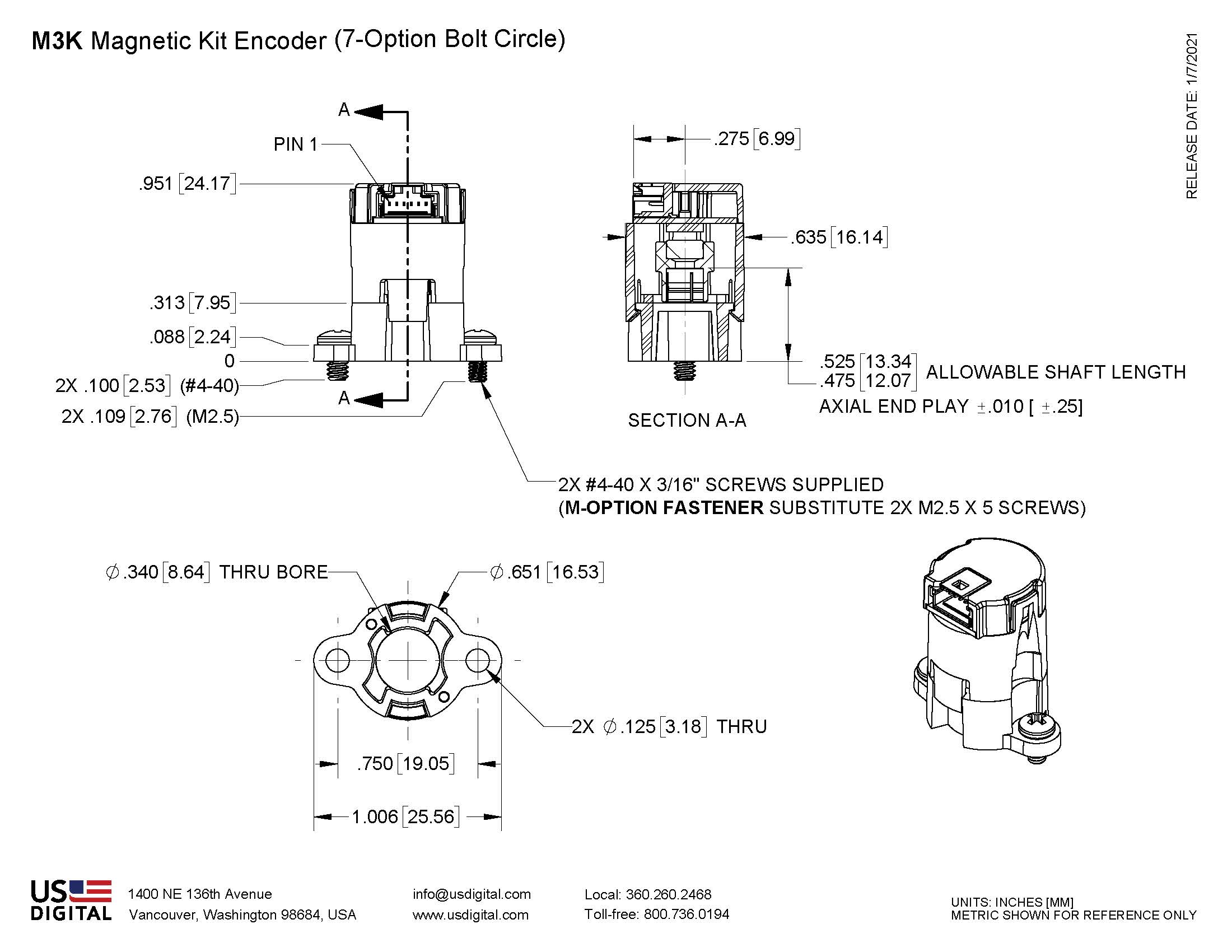
Mechanical Drawings

Specifications
ENVIRONMENTAL
| PARAMETER | VALUE | UNITS |
|---|---|---|
| Operating Temperature | -40 to 100 | C |
| Electrostatic Discharge, IEC 61000-4-2 | ±1 | kV |
| Vibration (10Hz to 2kHz, sinusoidal) | 20 | G |
| Shock (6 milliseconds, half-sine) | 75 | G |
MECHANICAL
| PARAMETER | VALUE | UNITS |
|---|---|---|
| Shaft Length (1) 0.586" bolt circle (5-option) 0.750" bolt circle (7-option) |
0.39 ± 0.035 0.5 ± 0.035 |
in. |
| Max. Shaft Axial Play | ±0.010 | in. |
| Max. Shaft Runout | 0.004 T.I.R. | in. |
| Max. Acceleration | 250,000 | rad/sec² |
| Max Hub Moment of Inertia | 9.4 x 10⁻⁷ | oz-in-s² |
| Bolt Circle Diameter Tolerance | ±0.005 | in. |
| Mounting Screw Size 0.586 bolt circle (5-option) 0.750" bolt circle (7-option) Metric (M-option) |
#3-48 x 3/16" #4-40 x 3/16" M2.5 x 5mm |
|
| Mounting Screw Torque 0.586" bolt circle (5-option) 0.750" bolt circle (7-option) Metric (M-option) |
2 to 3 4 to 6 2 to 3 |
in-lbs |
(1) Including axial play.
Download Technical Bulletin TB1001 - Shaft and Bore Tolerances
ELECTRICAL
| PARAMETER | MIN. | TYP. | MAX. | UNITS | NOTES |
|---|---|---|---|---|---|
| Supply Voltage | 4.0 | 5.0 | 16.5 | V | |
| Supply Current | 17 | mA | no load, 5V power | ||
| Low-level Output, A/B/Index |
0.02 |
0.4 | V | IOL= 4mA no load |
|
| High-level Output, A/B/Index |
4.0 | 4.8 |
V | IOL= -4mA no load |
|
| Low-level Output, PWM |
0.5 0.2 |
V | IOL= 0.5mA no load |
||
| High-level Output, PWM |
2.5 4.9 |
V | IOL= -0.5mA no load |
||
| Output Rise/Fall Time, A/B/Index |
25 | nS | no load | ||
| Output Rise Time, PWM |
1 | µS | no load | ||
| Output Fall Time, PWM |
25 | nS | no load | ||
| 12-bit PWM Frequency | 2.0 | kHz | Values up to 3.125 kHz available on request. Contact tech support. | ||
| PWM Duty Cycle range for 360 deg rotation | 5 | 95 | % |
- Typical values are specified at Vcc = 5.0V and 25C.
- A/B/Index outputs remain at 5V logic levels for Vcc > 5.0V
- PWM output is open-drain with 5k pullup to Vcc. The output is clamp limited to 6.5V Typ. for Vcc >5.0V
| CPR | Max RPM (1) | Typical Count Jitter ± 2σ limits x4 quadrature decoding | Typical Angle Jitter ± 2σ limits x4 quadrature decoding |
|---|---|---|---|
|
1 |
18720 |
0 counts |
0 deg. |
|
2 |
18720 |
0 |
0 |
|
4 |
18720 |
0 |
0 |
|
8 |
18720 |
0 |
0 |
|
16 |
18720 |
0 |
0 |
|
32 |
18720 |
0 |
0 |
|
64 |
18720 |
0 |
0 |
|
128 |
18720 |
0 |
0 |
|
256 |
18720 |
0 |
0 |
|
512 |
14648 |
± 1 |
± 0.18 |
|
1024 |
7324 |
± 1.4 |
± 0.12 |
|
2048 |
3662 |
± 1.4 |
± 0.062 |
|
4096 |
1831 |
± 2.1 |
± 0.05 |
|
8192 |
915 |
± 3.3 |
± 0.04 |
(1) minimum of 50 position samples per revolution
TIMING CHARACTERISTICS
| PARAMETER | SYMBOL | MIN. | TYP. | MAX. | UNITS |
|---|---|---|---|---|---|
| Symmetry | X, Y | 180 | °e | ||
| Quadrature | Z | 90 | °e | ||
| Index Pulse Width | Po | 90 | °e | ||
| Ch. I Rise After Ch. B or Ch. A Fall | t1 | 10 | ns | ||
| Ch. I Fall After Ch. B or Ch. A Rise | t2 | 10 |
ns |
TIMING DIAGRAM

- CPR
- The number of Cycles (C) of the A or B outputs Per Revolution.
- Index (I)
- The index output goes high once per revolution, coincident with the low states of channels A and B, nominally 1/4 of one cycle (90°e).
- One Shaft Rotation
- 360 mechanical degrees.
- One Electrical Degree (°e)
- 1/360th of one cycle.
- One Cycle (C)
- 360 electrical degrees (°e). Each cycle can be decoded into 1, 2, or 4 states, referred to as x1, x2, or x4 resolution multiplication.
- PPR
- The number of resolvable Positions Per Revolution of the encoder disk with x4 quadrature decoding.
- Quadrature (Z)
- The phase lag or lead between channels A and B in electrical degrees, nominally 90°e.
- Symmetry
- A measure of the relationship between (X) and (Y) in electrical degrees, nominally 180°e.
PIN-OUTS
| PIN | DESCRIPTION |
|---|---|
| 1 | Ground |
| 2 | Index |
| 3 | B channel |
| 4 | +4~16.5VDC power |
| 5 | A channel |
| 6 | PWM |
INCLUDED ACCESSORIES
1. CENTERING TOOL*
- Part #: CTOOL - M3K - (Shaft Diameter)
- Description: This reusable tool is used to accurately center the M3K base on the shaft.
2. SCREWS
- Part #: SCREW-348-188-PH
- Description: Pan Head, Philips #3-48 UNC x 3/16"
Use: Base Mounting
Quantity Required: 2
Screws are included
- Part #: SCREW-440-118-PH
- Description: Pan Head, Philips #4-40 UNC x 3/16"
Use: Base Mounting
Quantity Required: 2
Screws are included
- Part #: SCREW-M25-5MM-PH
- Description: Pan Head, Philips, M2.5 x 0.45 x 5MM
Use: Base Mounting
Quantity Required: 2
Screws are included
Notes
- US Digital® warrants its products against defects in materials and workmanship for two years. See complete warranty for details.
Configuration Options |
|||||||||||||||||||||||||||||||||||||||||||||
| M3K | - | Output I (Incremental) P (PWM & Incremental) | - | CPR (Cycles Per Revolution) 1 2 4 8 16 32 64 128 256 512 1024 2048 4096 8192 | - | Voltage 5 (5V) | - | Bore Size 118 (3.0mm) 125 (1/8") 157 (4.0mm) 188 (3/16") 197 (5.0mm) 236 (6.0mm) 250 (1/4") | - | Bolt Circle 5 (0.586") 7 (0.750") | - | Fastener S (Standard) M (Metric) | - | Packaging B (Encoders packaged in bulk. Every order includes one centering tool. An additional centering tool is included for each 100 encoders ordered.) 1 (Encoders packaged individually. Every order includes one centering tool. An additional centering tool is included for each 100 encoders ordered.) 2 (Encoders packaged individually. Every order includes one centering tool per encoder.) | |||||||||||||||||||||||||||||||
|
PLEASE NOTE: This chart is for informational use only. Certain product configuration combinations are not available. Visit the M3K product page for pricing and additional information. |
|||||||||||||||||||||||||||||||||||||||||||||