EC35 Features
- Kit version for mounting on a motor or other rotating shaft
- U/V/W commutation outputs (differential or open-collector)
- 0-12 poles or custom
- 11 Resolutions from 500 to 60,000 CPR (2,000 to 240,000 PPR)
- For NEMA 17 to 34 and larger motors
- Supports 5 shaft sizes (5 to 8 mm and 1/4 to 3/8 in.)
- Index output is standard
- High retention cable (sold separately)
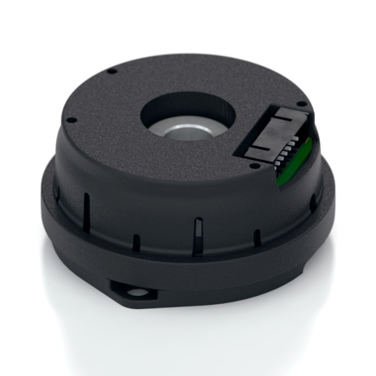
US Digital EC35 Motor Encoder Description
The US Digital EC35 motor encoder mounts directly to a motor but can also be installed on any rotating shaft. This incremental encoder uses a specially patterned optical disk on a precision-machined aluminum hub. In addition to a quadrature and differential index output, this encoder also provides a commutation output (differential or open-collector) for brushless motors with various pole counts.
This disk, in combination with an IC detector, creates a system that provides high resolution up to 60,000 CPR and is tolerant to mechanical misalignment. A push-on hub design securely grips the shaft without set screws, and a robust, glass-filled polymer housing provides easy installation in space-limited applications.
A built-in, removable spacer tool ensures that the encoder disk is automatically set to the correct gap when the encoder housing is mounted. The encoder can be "timed" by rotating a ring on the assembly and pressing the ring in with a simple tool to lock everything into place.
This optical encoder is designed for use with a high-retention connector. After making each selection in the Product Configurator, a compatible cable will be displayed below and must be purchased separately.
Please Note: Due to the EC35's design, it is recommended for use as a one-time installation.
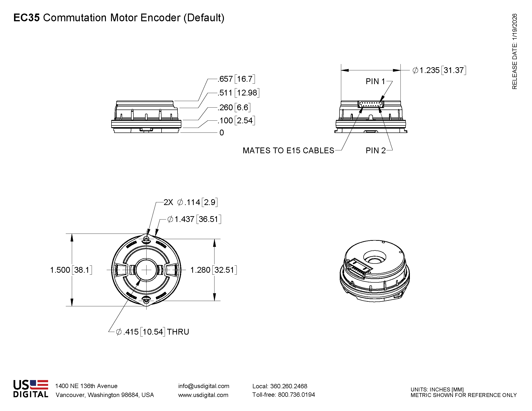
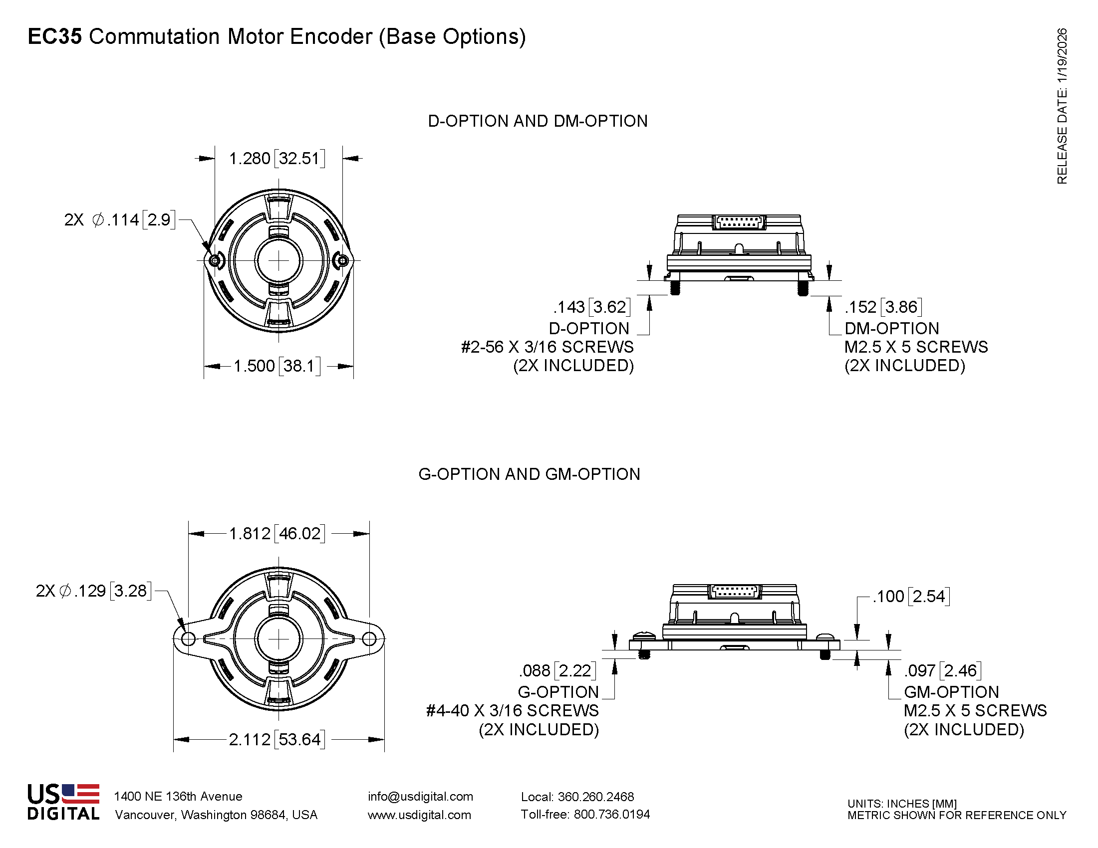
Mechanical Drawings
Specifications
ENVIRONMENTAL
| PARAMETER | PARAMETER | UNITS |
|---|---|---|
| Operating Temperature | -20 to 105 | C |
| Electrostatic Discharge, IEC 61000-4-2 | ±12 | kV |
| Vibration (10Hz to 2kHz, sinusoidal) | 20 | G |
| Shock (6 milliseconds, half-sine) | 75 | G |
MECHANICAL
| PARAMETER | VALUE | UNITS |
|---|---|---|
| Max. Shaft Axial Play | ±0.003 | in. |
| Max. Shaft Runout | 0.001 T.I.R. | in. |
| Max. Acceleration | 250000 | rad/sec² |
| Maximum RPM, CPR ≤ 2500 e.x. CPR = 2500, max. rpm = 9600 |
((24 x 10^6) / CPR) | RPM |
| Maximum RPM, CPR = 4000 | 12000 | RPM |
| Maximum RPM, CPR = 5000 | 9600 | RPM |
| Maximum RPM, CPR = 10000 | 6000 | RPM |
| Maximum RPM, CPR = 20000 | 3000 | RPM |
| Maximum RPM, CPR = 40000 | 1440 | RPM |
| Maximum RPM, CPR = 60000 | 960 | RPM |
| Codewheel Moment of Inertia | 6.48 x 10⁻⁵ | oz-in-s2 |
| Required Shaft Length | 0.500 to 0.565 | in. |
| Mounting Screw Torque | 2-3 | in-lbs |
| Technical Bulletin TB1001 - Shaft and Bore Tolerances | Download | |
ELECTRICAL
| SPECIFICATIONS | MIN. | TYP. | MAX. | UNITS | NOTES |
|---|---|---|---|---|---|
| Supply Current CPR ≤ 2500 CPR > 2500 |
13 37 |
17 44 |
mA |
no output load, max. frequency output |
|
| Supply Voltage | 4.5 | 5.0 | 5.5 | V | |
| Differential High Level Output | 2.5 | 3.5 | V | loh = -8 mA | |
| Differential Low Level Output | 0.5 | V | lol = 8 mA | ||
| Differential Rise/Fall Time | 100 | ns | |||
| Open collector pullup voltage | 30 | V | lload = 100 mA | ||
| Open collector "on" resistance | 0.2 | ohm | lload = 100 mA | ||
| Frequency Response, CPR ≤ 2,500 |
400 | kHz | |||
| Frequency Response, CPR = 4,000 & 5000 |
800 | kHz | |||
| Frequency Response, CPR = 10,000 |
1 | MHz | |||
| Frequency Response, CPR = 20,000 / 40,000 / 60,000 |
960 | kHz |
INCREMENTAL OUTPUT TIMING

| PARAMETER | MIN. | TYP. | MAX. | UNITS |
|---|---|---|---|---|
| Symmetry, S1, S2 | 108 | 180 | 252 | elec. deg. |
| Quadrature Delay, Q | 45 | 90 | 135 | elec. deg. |
| Index Width, W | 45 | 90 | 135 | elec. deg. |
A leads B for CCW shaft rotation, and B leads A for CW rotation viewed from the top side of the encoder.
ACCESSORIES
Screws:
Part #: SCREW-256-188-SH
Description: Socket Head Cap, #2-56 UNC x 3/16"
Use: Base Mounting
Quantity Required: 2
Screws are included
Part #: SCREW-M25-5MM-PH
Description: Pan Head, Phillips M2.5 x 0.45 x 5mm
Use: Base Mounting
Quantity Required: 2
Part #: SCREW-M25-5MM-BH
Description: Button Head Cap, M2.5 x 0.45 x 5mm
Use: Base Mounting
Quantity Required: 2
Screws are included
COMMUTATION OUTPUT TIMING

| PARAMETER | MIN. | TYP. | MAX. | UNITS |
|---|---|---|---|---|
| State width, 4 pole | 27 | 30 | 33 | angular deg. |
| State width, 6 pole | 17 | 20 | 23 | angular deg. |
| State width, 8 pole | 12 | 15 | 18 | angular deg. |
| State width, 10 pole | 9 | 12 | 15 | angular deg. |
| State width, 12 pole | 7 | 10 | 13 | angular deg. |
PIN-OUTS
| Pin | "D" Output Option | "C" Output Option | "0" pole Option |
|---|---|---|---|
| 1 | A+ (A Quadrature) | A+ (A Quadrature) | A+ (A Quadrature) |
| 2 | A- | A- | A- |
| 3 | B+ (B Quadrature) | B+ (B Quadrature) | B+ (B Quadrature) |
| 4 | B- | B- | B- |
| 5 | Z+ (Index) | Z+ (Index) | Z+ (Index) |
| 6 | Z- | Z- | Z- |
| 7 | U+ (U Commutation) | U (Open collector) | no connection |
| 8 | U- | no connection | no connection |
| 9 | V+ (V Commutation) | V (Open collector) | no connection |
| 10 | V- | no connection | no connection |
| 11 | W+ (W Commutation) | W (Open collector) | no connection |
| 12 | W- | no connection | no connection |
| 13 | +5V power | +5V power | +5V power |
| 14 | GND | GND | GND |
| 15 | no connection | no connection | no connection |
Notes
- Cables and connectors are not included and must be ordered separately.
- US Digital® warrants its products against defects in materials and workmanship for two years. See complete warranty for details.
Configuration Options |
|||||||||||||||||||||||||||||||||||||||||||||
| EC35 | - | CPR (Cycles Per Revolution) 500 1000 1250 2000 2500 4000 5000 10000 20000 40000 60000 | - | Motor Poles 0 4 6 8 10 12 | - | Bore Size 197 (5.0mm) 236 (6.0mm) 250 (1/4") 315 (8.0mm) 375 (3/8") | - | Index Gating H (A/B High) L (A/B Low) | - | Output C (Open-Collector U/V/W) D (Differential U/V/W) | - | Base D (1.28" Diameter Bolt Circle, #2-56 x 3/16" Screws) DM (1.28" Diameter Bolt Circle, M2.5 x 5 Screws) G (1.812" Diameter Bolt Circle, #4-40 x 3/16" Screws) GM (1.812" Diameter Bolt Circle, M2.5 x 5 Screws) | - | Packaging B (Bulk) | |||||||||||||||||||||||||||||||
|
PLEASE NOTE: This chart is for informational use only. Certain product configuration combinations are not available. Visit the EC35 product page for pricing and additional information. |
|||||||||||||||||||||||||||||||||||||||||||||