HB6M Features
- Hollow bore (hollow shaft/thru-bore) bearing design
- Rugged anodized aluminum housing
- Heavy-duty ball bearings track up to 6,000 RPM
- Positive latching polarized connector
- 2-channel quadrature with optional index
- Multiple Output Drive Options
- 64 to 10,000 cycles per revolution (CPR); 256 to 40,000 pulses per revolution (PPR)
HB6M Product Description
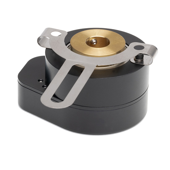
The HB6M is a high-resolution hollow bore (hollow shaft/thru-bore) optical encoder with a machined aluminum enclosure and an anodized protective finish. The HB6M optical incremental encoder is designed to easily mount to an existing shaft to provide digital feedback information. Typical applications include motor feedback, process control, robotics, textile machines, and elevator controls.
The HB6M bearing style encoder features a hollow bore that accepts shaft diameters from 0.236 in. to 0.750 in. in diameter. The encoder slips over the shaft and is locked into place with two 6-32 set screws. A flexible anti-rotation mount makes the encoder more tolerant of shaft runout than a standard kit encoder. The HB5M can accommodate shaft axial play up to ±0.030 in. and shaft runout up to 0.010 in. The flexible tether provides single-point mounting for bolt circle diameters from 2.5 in. to 5.0 in.
The HB6M housing comes standard with a closed cover or an optional hole in the body to allow a shaft to pass completely through the encoder.
A secure connection to the HB6M Series encoder is made through a 5-pin (single-ended versions) or 10-pin (differential, high-voltage or open-collector versions) latching connector. The mating connectors are available from US Digital with several cable options and lengths.
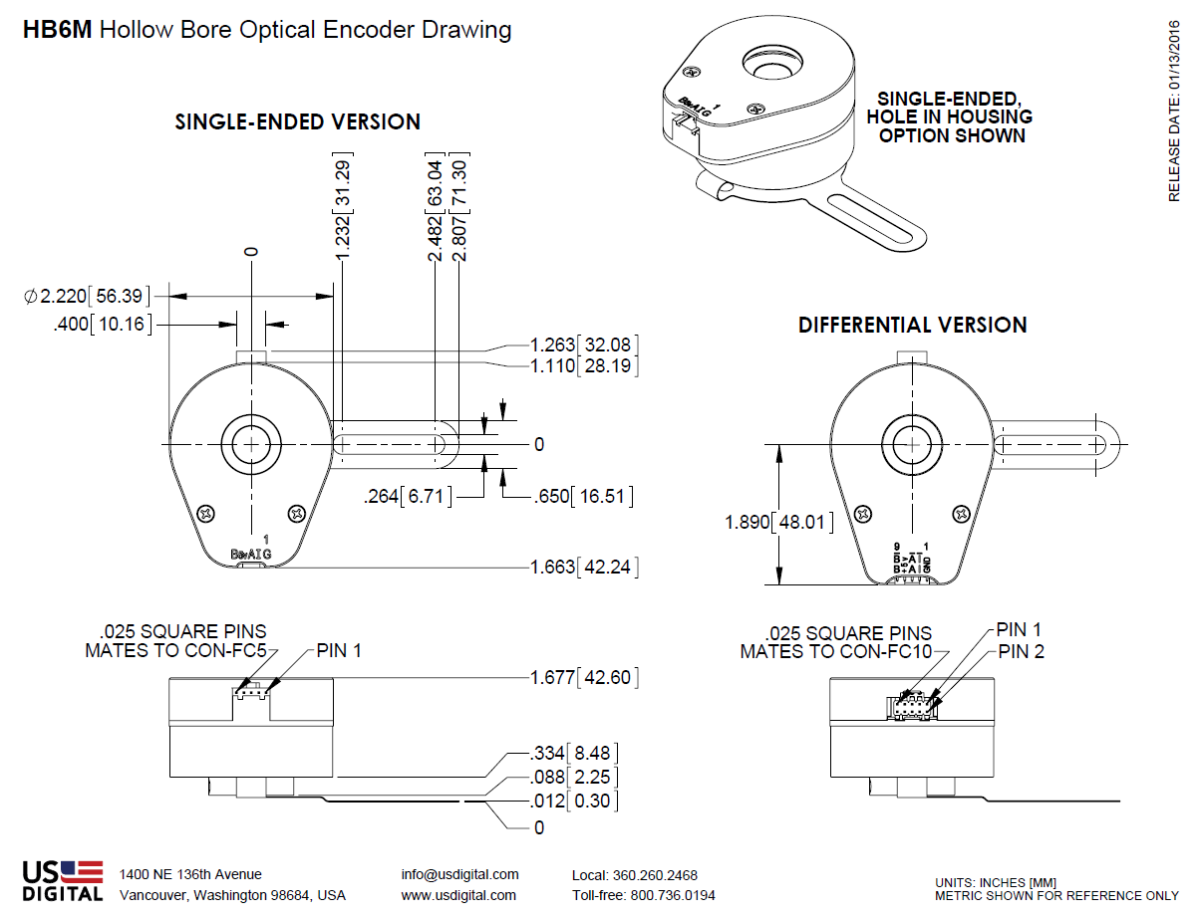
Mechanical Drawings
Specifications
ENVIRONMENTAL
| PARAMETER | VALUE | UNITS |
|---|---|---|
| Operating Temperature (CPR < 3600) | -40 to 100 | C |
| Operating Temperature (CPR ≥ 3600) | -25 to 100 | C |
| Electrostatic Discharge Single-ended (-S version), IEC 61000-4-2 Differential (-D version), Human Body Model High-Voltage, Open-collector (H, C option), IEC 61000-4-2 |
± 4 ± 2 ± 4 |
kV |
| Vibration (10Hz to 2kHz, sinusoidal) | 20 | G |
| Shock (6 milliseconds, half-sine) | 75 | G |
MECHANICAL
| PARAMETER | DIMENSION |
|---|---|
| Max. Acceleration | 100000 rad/sec² |
| Max. Shaft Speed | 6000 rpm |
| Max. Starting Torque | 0.70 oz-in |
| Max. Bore Loading | 5 lb. |
| Weight | 11.5 oz. |
| Max. Shaft Runout | 0.010 in. T.I.R. |
| Max. Shaft Axial Play | ± 0.030 in. |
| Required Shaft Length (From mounting surface) | Min. = 0.3 in. Max. = 1.4 in. with default cover. Max. = No limit with H-option cover. |
| Moment of Inertia | 3.7x10^-3 oz-in-sec² |
| Technical Bulletin TB1001 - Shaft and Bore Tolerances | Download |
TETHER MOUNTING
The tether is shipped detached and may be mounted in the four different methods as shown below.

PHASE RELATIONSHIP
A leads B in a clockwise shaft rotation, and B leads A in counterclockwise shaft rotation viewed from the rear side (opposite flexible mount) of the encoder.
SINGLE-ENDED OPTION
- S option provides 5V TTL compatible outputs
- Specifications apply over the entire operating temperature range
- Typical values are specified at Vcc = 5.0Vdc and 25°C
- For complete details, see the EM1 and EM2 product pages
| PARAMETER | MIN. | TYP. | MAX. | UNITS | CONDITIONS |
|---|---|---|---|---|---|
| Supply Voltage | 4.5 | 5.0 | 5.5 | V | |
| Supply Current | 27 | 33 | mA | CPR < 1000, no load | |
| 54 | 62 | mA | CPR ≥ 1000 and < 3600, no load | ||
| 72 | 85 | mA | CPR ≥ 3600, no load | ||
| Low-level Output | 0.5 | V | IOL = 8mA max., CPR < 3600 | ||
| 0.5 | V | IOL = 5mA max., CPR ≥ 3600 | |||
| 0.05 | V | no load, CPR < 3600 | |||
| 0.25 | V | no load, CPR ≥ 3600 | |||
| High-level Output | 2.0 | V | IOH = -8mA max., CPR < 3600 | ||
| 2.0 | V | IOH = -5mA max., CPR ≥ 3600 | |||
| 4.8 | V | no load, CPR < 3600 | |||
| 3.5 | V | no load, CPR ≥ 3600 | |||
| Output Current Per Channel | -8 | 8 | mA | CPR < 3600 | |
| -5 | 5 | mA | CPR ≥ 3600 | ||
| Output Rise Time | 110 | nS | CPR < 3600 | ||
| 50 | nS | CPR ≥ 3600 | |||
| Output Fall Time | 35 | nS | CPR < 3600 | ||
| 50 | nS | CPR ≥ 3600 |
DIFFERENTIAL OPTION
- D Option provides differential line driver output
- Specifications apply over the entire operating temperature range
- Typical values are specified at Vcc = 5.0Vdc and 25°C
- For complete details, see the EM1 and EM2 product pages
| PARAMETER | MIN. | TYP. | MAX. | UNITS | CONDITIONS |
|---|---|---|---|---|---|
| Supply Voltage | 4.5 | 5.0 | 5.5 | V | |
| Supply Current | 29 | 36 | mA | CPR < 1000, no load | |
| 56 | 65 | mA | CPR ≥ 1000 and < 3600, no load | ||
| 74 | 88 | mA | CPR ≥ 3600, no load | ||
| Low-level Output | 0.2 | 0.4 | V | IOL = 20mA max. | |
| High-level Output | 2.4 | 3.4 | V | IOH = -20mA max. | |
| Differential Output Rise/Fall Time | 15 | nS |
HIGH-VOLTAGE OPTION
- H option uses a higher supply voltage and provides both single-ended and open-collector outputs
- Single-ended outputs are 5V TTL compatible (same as S option). See Pin-out.
- Specifications apply over the entire operating temperature range
- For complete details, see the EM1 or EM2 product pages
| PARAMETER | MIN. | TYP. | MAX. | UNITS | CONDITIONS |
|---|---|---|---|---|---|
| Supply Voltage | 7.5 | 30.0 | V | ||
| Supply Current, 24V power | 8 | 10 | mA | CPR < 500, no load | |
| 16 | 19 | mA | CPR ≥ 500 and < 2000, no load | ||
| 22 | 25 | mA | CPR ≥ 2000, no load | ||
| Open Collector "On" Resistance | 2 | ohms | |||
| Open Collector Sink Current | 200 | mA | |||
| Output Low Voltage | 0.4 | V | 200 mA sink current | ||
| Open Collector Pullup Voltage | 50 | V |
PIN-OUTS
|
5-PIN SINGLE-ENDED |
10-PIN DIFFERENTIAL D OPTION (2) |
||
|---|---|---|---|
| Pin | Description | Pin | Description |
| 1 | Ground | 1 | Ground |
| 2 | Index | 2 | Ground |
| 3 | A channel | 3 | Index- |
| 4 | +5VDC power | 4 | Index+ |
| 5 | B channel | 5 | A- channel |
| 6 | A+ channel | ||
| 7 | +5VDC power | ||
| 8 | +5VDC power | ||
| 9 | B- channel | ||
| 10 | B+ channel | ||
| 10-PIN HIGH-VOLTAGE H OPTION (2) |
|
|---|---|
| Pin | Description |
| 1 | Ground |
| 2 | Ground |
| 3 | Index- (open collector) |
| 4 | Index+ (single-ended) |
| 5 | A- channel (open collector) |
| 6 | A+ channel (single-ended) |
| 7 | 7.5-30V power |
| 8 | 7.5-30V power |
| 9 | B- channel (open collector) |
| 10 | B+ channel (single-ended) |
(1) 5-pin single-ended mating connector is CON-FC5.
(2) 10-pin differential mating connector is CON-FC10.
Notes
- Cables and connectors are not included and must be ordered separately.
- US Digital® warrants its products against defects in materials and workmanship for two years. See complete warranty for details.
Configuration Options |
||||||||||||||||||||||||||||||||||||||||||||||||
| HB6M | - | CPR (Cycles Per Revolution) 64 100 200 400 500 512 1000 1024 1800 2000 2048 2500 3600 4000 4096 5000 7200 8000 8192 10000 | - | Bore Size 236 (6.0mm) 250 (1/4") 313 (5/16") 315 (8.0mm) 375 (3/8") 394 (10.0mm) 472 (12.0mm) 500 (1/2") 551 (14.0mm) 625 (5/8" Bore) 750 (3/4" Bore) | - | Index IE (Index) NE (Non-Index) | - | Output S (Single-Ended) H (Single-Ended High-Voltage) D (Differential) | - | Housing D (Default) H (Hole in Cover) | ||||||||||||||||||||||||||||||||||||||
|
PLEASE NOTE: This chart is for informational use only. Certain product configuration combinations are not available. Visit the HB6M product page for pricing and additional information. |
||||||||||||||||||||||||||||||||||||||||||||||||