MA4 Features
- 12-bit Analog or PWM output
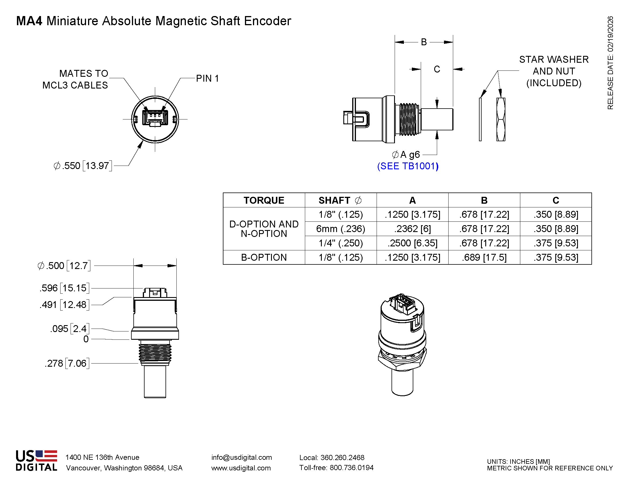
- Miniature size (0.55 in. diameter)
- -40C to 125C operating temperature range
- Latching Connector
- Three shaft torque options*
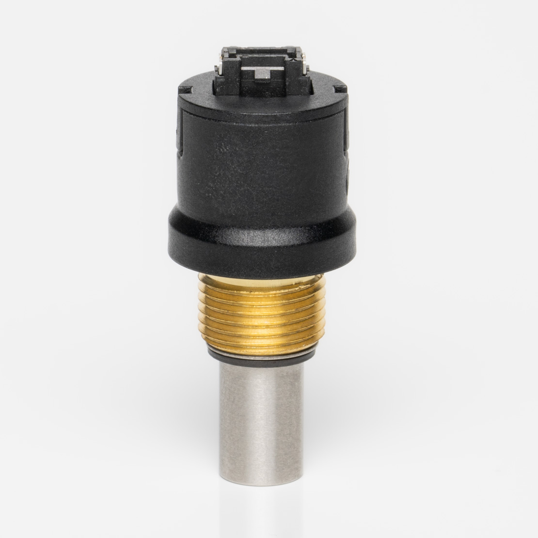
MA4 Miniature Absolute Encoder Product Description
The MA4 is a magnetic absolute encoder that reports the shaft position over 360° with no stops or gaps. This shafted encoder is available with an analog or a pulse width modulated (PWM) digital output. This is the new generation of the US Digital MA3 absolute encoder, magnetic.
Analog output provides a DC voltage that is proportional to the absolute shaft position with 12-bit resolution.
PWM output provides a pulse duty cycle that is proportional to the absolute shaft position. PWM output has 12-bit resolution with 2 different output frequency options.
Three shaft torque options are available:
- Default (-D): sleeve bushing with higher damping for human interface applications.
- Ball bearing (-B): miniature precision ball bearings suitable for high-speed applications (1/8" diameter shaft only).
- Light static drag (-N): sleeve bushing with lower damping for low-speed applications.
The MA4 is connected using a 3-pin latching, 1.25mm pitch polarized connector.
*There are three torque options for the 1/8 in. shaft and two options for the 1/4 in. and 6 mm shaft sizes.
Mechanical Drawings
Specifications
ENVIRONMENTAL
| PARAMETER | VALUE | UNITS |
|---|---|---|
| Operating Temperature | -40 to +125 | C |
| Vibration (10Hz to 2kHz, sinusoidal) | 20 | G |
| Shock (6 milliseconds, half-sine) | 75 | G |
| Electrostatic Discharge, IEC 61000-4-2 | ± 4 | kV |
MECHANICAL
| SPECIFICATION | SLEEVE BUSHING | BALL BEARING |
|---|---|---|
| Max. Shaft Speed (1)(mechanical) | 100 RPM | 15000 RPM |
| Max. Acceleration | 10000 rad/sec² | 250000 rad/sec² |
| Max. Shaft Torque | 0.5 in-oz (D-option) 0.3 in-oz (N-option) |
0.05 in-oz (B-option) |
| Max. Shaft Loading | 2 lb. dynamic 20 lb. static |
1 lb. |
| Bearing Life (2) | > 1000000 revolutions | L10 = (28.3/Fr)³ Where L10 = bearing life in millions of revs, and Fr = radial shaft loading in pounds |
| Weight | 0.42 oz. | 0.31 oz. |
| Max. Shaft Runout | 0.0015 in. T.I.R. | 0.0015 in. T.I.R. |
(1) The chip that decodes position uses sampled data. There will be fewer readings per revolution as the speed increases. The formula for number of readings per revolution is given by:
n = 400000 / rpm
(2) only valid with negligible axial shaft loading
MOUNTING
| PARAMETER | VALUE | UNITS |
|---|---|---|
| Hole Diameter | 0.375 +0.005 / -0.0 | in. |
| Panel Thickness | 0.125 max. | in. |
| Panel Nut Max. Torque | 20.0 | in-lbs |
MATERIALS
| COMPONENT | MATERIAL | TORQUE OPTION(S) |
|---|---|---|
| Shaft | Stainless Brass |
Sleeve Bushing (-D and -N options) Ball Bearing (-B option only) |
| Bushing | Brass | - |
MAGNETIC FIELD CROSSTALK
The MA4 absolute encoder contains a small internal magnet that generates a weak magnetic field extending outside the housing of each encoder. If two MA4 units are mounted closer than 1 inch apart (shaft center to center distance), install a magnetic shield such as a thin steel plate between the two encoders. This prevents magnetic field cross-talk from causing small changes in the reported positions.
ELECTRICAL
| PARAMETER | MIN. | TYP. | MAX. | UNITS |
|---|---|---|---|---|
| Power Supply | 4.5 | 5.0 | 5.5 | Volts |
| Supply Current | 16 | 20 | mA | |
| Power-up Time | 50 | mS |
ANALOG OUTPUT OPERATION

The analog output has 12-bit resolution. The analog output voltage is ratiometric to the power supply voltage, which is typically 5.0V. To prevent excessive jitter of the output at the 0 to 360 deg. transition point, 10-LSB of hysteresis is applied to the angle position at this point.
| PARAMETER | MIN. | TYP. | MAX. | UNITS |
|---|---|---|---|---|
| Position Sampling Rate | 6.667 | kHz | ||
| Propagation Delay | 286 | μS | ||
| Output Noise (1-σ) | 0.043 | Deg. RMS | ||
| Max Output Voltage no load 5k load to GND 2k load to GND |
4.99 4.97 4.92 |
V | ||
| Min Output Voltage no load 5k load to Vcc 2k load to Vcc |
0.010 0.030 0.075 |
V | ||
| Capacitive Load | 1000 | pF |
PWM OUTPUT OPERATION
The PWM duty cycle has 12-bit resolution. To measure the angular position accurately, calculate the position from the duty cycle (ton / (ton + toff )) instead of just measuring ton . This will cancel out the effect of the PWM frequency tolerance. To prevent excessive jitter of the output at the 0 to 360 deg. transition point, 10-LSB of hysteresis is applied to the angle position at this point.
| PARAMETER | MIN. | TYP. | MAX. | UNITS |
|---|---|---|---|---|
| PWM Frequency -L option -H option |
218 874 |
230 920 |
242 966 |
Hz |
| PWM Duty Cycle | 2.942 | 97.058 | % | |
| Position Sampling Rate | 6.667 | kHz | ||
| Propagation Delay | 286 | μS | ||
| Output Noise (1-σ) | 0.043 | Deg. RMS | ||
| Output High Voltage 10k load to GND 5k load to GND |
4.72 4.44 |
V | ||
| Output Low Voltage 10k load to Vcc 5k load to Vcc |
0.16 0.36 |
V | ||
| Capacitive Load | 1000 | pF |
.(1) PWM cycle time is 4351 internal clock periods. There are 4096 possible values of the duty cycle with a minimum value of (128/4351) and a maximum of (4223/4351).
PIN-OUTS
ANALOG OUTPUT (MA4-A):
| PIN | NAME | DESCRIPTION |
|---|---|---|
| 1 | 5 | +5VDC power |
| 2 | A | Analog output |
| 3 | G | Ground |
PWM OUTPUT (MA4-H, MA4-L):
| PIN | NAME | DESCRIPTION |
|---|---|---|
| 1 | 5 | +5VDC power |
| 2 | P | PWM output |
| 3 | G | Ground |
Notes
- Cables and connectors are not included and must be ordered separately.
- US Digital® warrants its products against defects in materials and workmanship for two years. See complete warranty for details.
Configuration Options |
|||||||||||||||
| MA4 | - | Output A (Analog) L (PWM Low) H (PWM High) | - | Shaft Diameter 125 (1/8") 236 (6mm) 250 (1/4") | - | Torque D (Default Torque) B (Ball Bearing) N (Light Static Drag) | |||||||||
|
PLEASE NOTE: This chart is for informational use only. Certain product configuration combinations are not available. Visit the MA4 product page for pricing and additional information. |
|||||||||||||||