A2K Features
- Installs onto shafts up to 10mm diameter
- 12-bit resolution, and resolution field programmable from 2 to 4,096 codes per revolution (3,600 factory default)
- Full 360 degrees range, 7 msec update time
- Low power drain of 18.5 mA max., and 2.5 mA in sleep mode
- Field programmable parameters such as setting zero position point (free demo software provided)
- EEPROM stores downloadable parameters
- 9,600 baud default data rate adjustable up to 115K baud
- 12-bit analog voltage output option (0 to +3.599 volts factory default setting. Field programmable up to 0 to +4.095 volts)
- Multi-turn mode (note: power must be maintained to prevent reset to zero)
- -25 to 70 degrees C. operating temperature
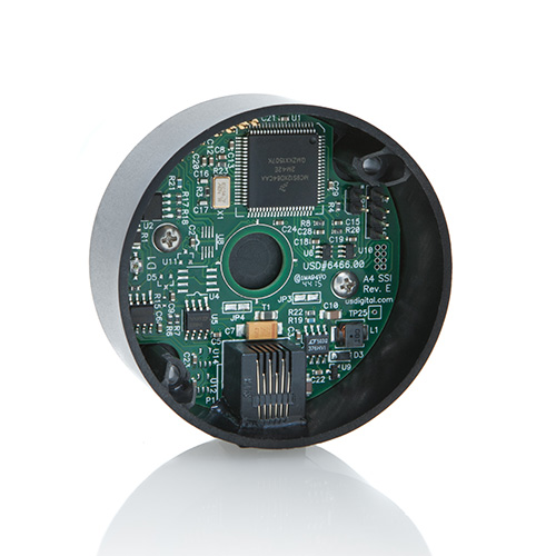
A2K Product Description
The A2K optical encoder is a 12-bit absolute rotary kit style encoder that reports a shaft angle within a single 360-degree rotation of a shaft. The kit style A2K allows the encoder to be easily assembled onto an existing shaft and bearing assembly. Unlike incremental, sometimes called relative, style encoders, the A2K provides true (absolute) shaft position eliminating the need for a home or zero cycle after a supply voltage power cycle. The A2K communicates over a RS 485 style serial bus utilizing US Digital's SEI (Serial Encoder Interface), which allows for simple, quick and convenient networking of multiple SEI devices on a single network. PLCs, motion controllers, and computers can also reside on the SEI bus by using US Digital's SEI to USB interface device. For complete information about the SEI bus, please refer to the SEI Communications Protocol webpage.
The A2K is also available with an optional analog output. The analog output option provides a maximum voltage range of 0 to 4.095 volts with 12-bit resolution. The output voltage can be scaled by simple SEI commands to provide user-defined voltage ranges. From the factory, the analog output voltage is set to 0 to 3.599 VDC range. Please note that with the A2K analog output option, only one device may reside on an SEI bus.
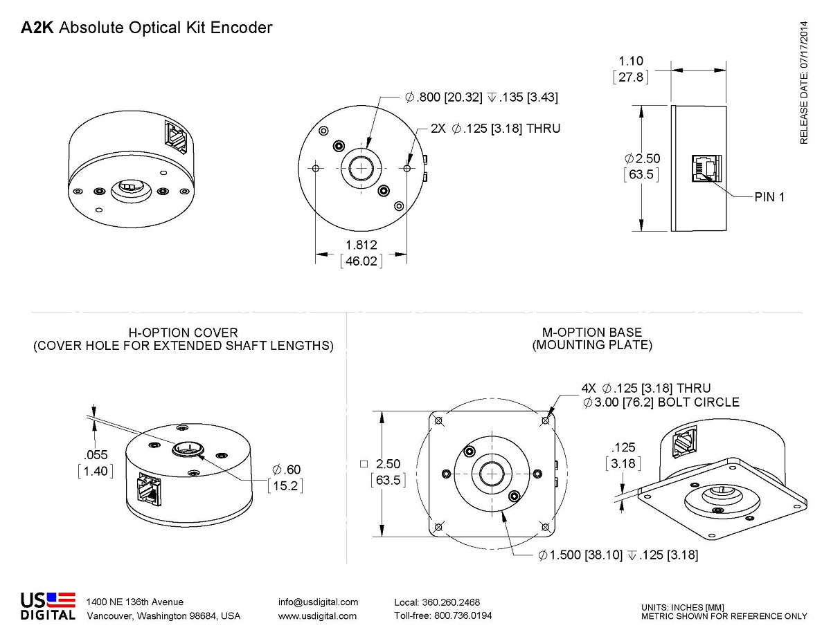
Mechanical Drawings
Specifications
ENVIRONMENTAL
| PARAMETER | VALUE | UNITS |
|---|---|---|
| Operating Temperature | -25 to 70 | C |
| Vibration (5Hz to 2kHz) | 20 | G |
| Electrostatic Discharge, IEC 61000-4-2 | ± 4 | kV |
MECHANICAL
| Parameter | Value | Units |
|---|---|---|
| Max. Shaft Axial Play | ±0.010 | in. |
| Max. Shaft Runout | 0.010 T.I.R. | in. |
| Max. Acceleration | 100000 | rad/sec² |
| Weight | 2.5 | oz. |
| Codewheel Moment of Inertia | 8.9 x 10^-5 | oz-in-s² |
| Max. Shaft Length | 0.60 to .80 from mounting surface | in. |
| Technical Bulletin TB1001 - Shaft and Bore Tolerances | Download |
ELECTRICAL
- Specifications apply over entire operating temperature range.
- Typical values are specified at Vcc = 12V and 25C.
| Parameter | Min. | Typ. | Max. | Units |
|---|---|---|---|---|
| Supply Voltage | 7.5 | 12 | 16 | V |
| Supply Current @ 12V supply Active Sleep |
14 2.5 |
18.5 |
mA |
|
| Analog Output Impedance | 51 | Ohms | ||
| Zero Scale Analog Voltage | 0 | 2 | 12 | mV |
| Full Scale Analog Voltage | 4.066 | 4.095 | 4.124 | V |
| Output Noise (Analog version) | 10 | mV rms | ||
| Differential Nonlinearity (Analog version) | -1.0 | 1.0 | LSB | |
| Integral Nonlinearity (Analog version) | -1.0 | 1.0 | LSB | |
| Absolute Accuracy (SEI interface version) | 0.18 | 0.25 | Degrees | |
| Angle tracking speed Single-turn mode Multi-turn mode |
3600 1800 |
RPM |
||
| Position Update Rate (1) | 7 | msec. |
(1) The internal microcontroller takes a snapshot of the disk every 7 msec. and stores the position in memory. It responds immediately to a "report position request" by sending the most recently computed position.
DEFAULT SETTINGS
| Parameter | Default value | Volatile? |
|---|---|---|
| SEI address | 2 | Non-volatile |
| Resolution | 3600 | Non-volatile |
| Origin offset | 0 | Non-volatile |
| Baud rate | 9600 | Volatile |
| Mode | 0 | (1) |
(1) Mode is always restored from non-volatile EEPROM on power-up. However, there are separate SEI commands for setting the RAM copy only, or both the RAM copy and the non-volatile EEPROM copy. For an explanation of the Mode bits see SEI Absolute Encoder Communications Protocol.
SEI NETWORK

ANALOG OUTPUT
The analog version of the A2K has a 12-bit DAC on the output which feeds to 2 lines that are otherwise used for the BUSY handshaking pair. This DAC has a full range of 0 to 4.095 Volts which is 1 mV per bit. The absolute position value which the internal microcontroller sends to that DAC is the same as the digital value that it sends to the host over SEI. Since the resolution (which represents the number of codes per revolution) is field programmable, the range of the DAC will also follow that setup. The default resolution is 3600 codes per revolution which yields 1 count per a tenth of a degree. This makes the DAC output equal to 1 mV per tenth of a degree or 0 to 3.599 Volts. When the DAC needs to have the full range to 4.095 Volts, the single turn resolution should be set to 4096. This is easily done with the available software which runs on a PC. Cable CA-MD6A-SS-MD6-6FT and the SEI-USB are needed to interface the A2K analog version to a USB port or RS-232 serial COM port.
Please Note: The BUSY handshaking lines are replaced by the analog output option. This means that only one device will be able to be connected to the SEI bus when using the analog output option.
PIN-OUTS
| PIN | DESCRIPTION |
|---|---|
| 1 | Ground |
| 2 | Busy+ Analog+ |
| 3 | Busy- Analog- |
| 4 | Power |
| 5 | DataL |
| 6 | DataH |
INCLUDED ACCESSORIES
Each A2K is shipped with all encoder components, centering tool, hex wrench, and two #4-40 x 1" cover screws. The following part numbers are provided if spares are needed.
1. Centering Tool
Part #: CTOOL - (Shaft Diameter)
Description: This reusable tool provides a simple method for accurately centering the A2K base onto the shaft.
Instructions: When mounting encoder base, slide centering tool down shaft until it slips into centering hole of encoder base. Tighten mounting screws, then remove centering tool.
2. Hex Tool
Part #: HEXD-050
Description: Hex driver, 0.050" flat-to-flat for #3-48 or #4-48 set screws.
Part #: HEXW-050
Description: Hex wrench, .050" flat-to-flat for #3-48 or #4-48 set screws.
3. Spacer Tool
Part #: SPACER-A2
TORQUE SPECIFICATIONS
| Parameter | Value | Units |
|---|---|---|
| Hub Set Screw | 2-3 | in-lbs |
| Cover Screw | 2-4 | in-lbs |
| Base Mounting Screw (#2-56) | 2-3 | in-lbs |
| Base Mounting Screw (#4-40) | 4-6 | in-lbs |
| Adapter Plate Mounting Screw (#2-56) | 2-3 | in-lbs |
| Adapter Plate Mounting Screw (#4-40) | 4-6 | in-lbs |
Notes
- Cables and connectors are not included and must be ordered separately.
- US Digital® warrants its products against defects in materials and workmanship for two years. See complete warranty for details.
Configuration Options |
|||||||||||||||||||||||||||
| A2K | - | Interface A (Analog) S (SEI) | - | Bore Size 079 (2.0mm) 118 (3.0mm) 125 (1/8") 156 (5/32") 157 (4.0mm) 188 (3/16") 197 (5.0mm) 236 (6.0mm) 250 (1/4") 313 (5/16") 315 (8.0mm) 375 (3/8") 394 (10.0mm) | - | Cover D (Default) H (Through-Hole) | - | Base D (Default) M (3" Diameter Bolt Circle) | |||||||||||||||||||
|
PLEASE NOTE: This chart is for informational use only. Certain product configuration combinations are not available. Visit the A2K product page for pricing and additional information. |
|||||||||||||||||||||||||||