ESWITCH Features
- Wide 6-25V supply range
- Covers most useful RPM ranges with 256 CPR encoder
- Simple DIP switch programming
- Isolated relay output
The ESWITCH is no longer available for purchase.
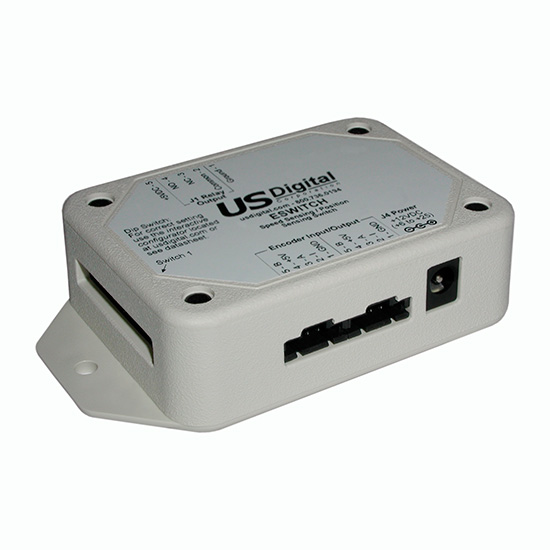
ESWITCH Product Description
The ESWITCH is an encoder speed/position sensing device with an isolated SPDT relay output. This product uses incremental encoder feedback to serve as a speed switch or as a position switch. The relay will be activated for 1 second when the speed threshold is exceeded or if the position deviates from the present position by a programmable threshold. Two encoder connectors are provided in parallel to make it convenient to loop the encoder signals through the ESWITCH. A series of 12 DIP switches program the ESWITCH. DIP switch 12 is not used.
Mechanical Drawings
Specifications
ELECTRICAL
| PARAMETER | MIN. | TYP. | MAX. | UNITS | NOTES |
|---|---|---|---|---|---|
| Supply Voltage | 6 | 25 | V | ||
| Supply Current | 110 | mA | 12V power, no encoders | ||
| Voltage Out to Encoder | 4.8 | 5.0 | 5.2 | V | @100mA load |
| Encoder Current | 250 | mA | 5V power out for encoder | ||
| Quadrature Input Frequency | 400 | kHz | |||
| Quadrature Encoder Inputs - Logic Low | 0 | 0.4 | 0.8 | V | Diode clamped to ground, 5k pullup to 5V |
| Quadrature Encoder Inputs -Logic High | 2.0 | 5.0 | 5.75 | V | Diode clamped to ground, 5k pullup to 5V |
| Relay Contact Rating | 2.0 | A | External "catch" diode should be used for inductive loads | ||
| Relay Dielectric Strength | 500 500 |
VAC VAC |
Open contacts Contacts to Coil |
||
| Relay Contact Resistance | 100 | uohms |
- The ESWITCH is normally powered through the power connector, but it may also be powered via J1, pin 5.
SPEED SENSING MODE
DIP Switch SW11 = "up" for this mode.
In speed sensing mode, the relay will activate for approximately 1 second when the sensed RPM is equal to or greater than the RPM threshold. DIP Switches SW1 to SW10 are used to set the threshold value. The output relay has both normally open and normally closed contacts available to the user.
The CPR of the encoder must be chosen according to the desired RPM range:
| ENCODER CPR | RPM RANGE |
|---|---|
| 200 | 28 to 7004 |
| 256 | 21 to 5470 |
| 512 | 11 to 2736 |
| 1024 | 6 to 1268 |
DIP switch SW10,SW9,SW8 setting:
Calculate the PRESET value from the desired RPM threshold, RPMT and the encoder CPR using the formula:
PRESET = 1920 / (RPMT * CPR)
Look up the SW10/SW9/SW8 setting based on the PRESET value using the table below and note the corresponding PREOUT constant value. If PRESET is outside the range of the table, lower the encoder CPR to get the value within range.
| PRESET RANGE | SW10 | SW9 | SW8 | PREOUT |
|---|---|---|---|---|
| 0.1747601 to 0.3495300 | ↓ | ↓ | ↓ | 0.3495300 |
| 0.0873811 to 0.1747600 | ↓ | ↓ | ↑ | 0.1747600 |
| 0.0436911 to 0.0873810 | ↓ | ↑ | ↓ | 0.0873810 |
| 0.0218451 to 0.0436910 | ↓ | ↑ | ↑ | 0.0436910 |
| 0.0109231 to 0.0218450 | ↑ | ↓ | ↓ | 0.0218450 |
| 0.0054614 to 0.0109230 | ↑ | ↓ | ↑ | 0.0109230 |
| 0.0027308 to 0.0054613 | ↑ | ↑ | ↓ | 0.0054613 |
| 0.0000000 to 0.0027307 | ↑ | ↑ | ↑ | 0.0027307 |
DIP Switch SW7 to SW1 setting:
Calculate the offset value as shown below:
OFFSETV = ( (RPMT * CPR * PREOUT) / 15 ) - 128
Convert the OFFSETV to binary and enter the value on SW7 to SW1. SW7 is the most significant bit. DIP Switch down = 0 and DIP Switch up = 1
POSITION SENSING MODE
DIP Switch SW11 = "down" for this mode.
In this mode, an internal up / down counter will decode quadrature states and track the position of the external encoder. DIP switches SW1 through SW7 allow the user to set the number of counts from 1 to 127 in binary. SW7 is the most significant bit. DIP Switch down = 0 and DIP Switch up = 1. The relay will be activated for about 1 second when the counter deviates from the current position by the programmed count value. The counter will auto-reset to zero whenever the trigger point is reached. The output relay has both normally open and normally closed contacts available to the user.
Example:
If the DIP switches are set to 12 in binary, then the relay output will be activated for 1 second when the shaft rotates 12 quadrature states in either direction. The shaft will need to deviate from the current position by 12 quadrature states to activate again.
PIN-OUTS
Encoder Input/Output
| PIN | DESCRIPTION |
|---|---|
| 1 | Ground |
| 2 | Index |
| 3 | A channel |
| 4 | +5V power |
| 5 | B channel |
J1 Connector
| PIN | DESCRIPTION |
|---|---|
| 1 | Ground |
| 2 | Relay Common Contact |
| 3 | Relay N.C. contact |
| 4 | Relay N.O. contacy |
| 5 | Input Supply Voltage |
INCLUDED ACCESSORIES
Notes
- Cables and connectors are not included and must be ordered separately.
- US Digital® warrants its products against defects in materials and workmanship for two years. See complete warranty for details.
Configuration Options |
| ESWITCH |
|
PLEASE NOTE: This chart is for informational use only. Certain product configuration combinations are not available. Visit the ESWITCH product page for pricing and additional information. |