ESUM Features
- Fast hardware solution
- Obtains sum or difference of 2 encoder positions
- DIN rail mount option
The ESUM is no longer available for purchase.
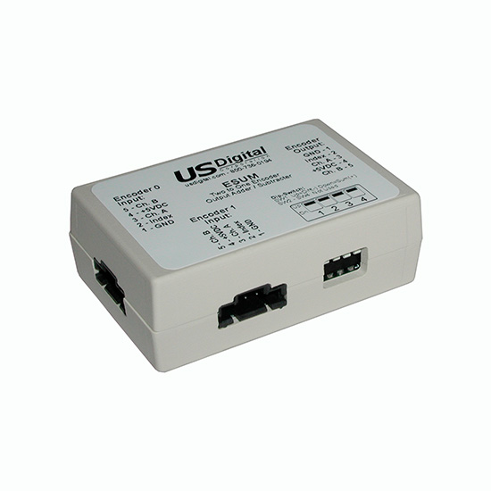
ESUM Product Description
The ESUM combines the quadrature outputs of two encoders into a single quadrature output. The output quadrature may be selected to be either the sum or difference of the two quadrature inputs. The index from encoder 0 is wired to the index of the output. The index from encoder 1 is not used. Connectors are 5-pin positive latching.
Applications for the ESUM include:
- Coarse and fine operator controls when one encoder is high resolution, and the other is low resolution.
- Measuring the difference in position between 2 shafts with one encoder is mounted on each.
- Measuring dynamic coupling twist with one encoder mounted on each side of the coupling.
The ESUM functions by sampling the two encoder inputs, decoding the quadrature inputs into up/down signals, combining the up/down signals, and synthesizing new quadrature on the output. The sampling nature of the operation limits the maximum quadrature frequency to 46.8 kHz.
To use, place the ESUM in line with the encoder cables. The ESUM derives its power from the +5V pin of the encoder cable. DIN rail mounting is available. Only SW1 affects the function of the ESUM. SW2, SW3, and SW4 are not used.
Mechanical Drawings
Specifications
ABSOLUTE MAXIMUM RATINGS
| PARAMETER | MIN. | MAX. | UNITS |
|---|---|---|---|
| Storage Temperature | -40 | 100 | C |
| Operating Temperature | 0 | 70 | C |
| Humidity (non-condensing) | 0 | 95 | % |
| Digital Inputs (diode clamped) | -0.6 | 5.6 | V |
ELECTRICAL
| PARAMETER | MIN. | TYP. | MAX. | UNITS |
|---|---|---|---|---|
| Supply Voltage (Vcc) | 4.75 | 5.0 | 5.25 | V |
| Supply Current (no encoders) | 120 | mA | ||
| Input Low Voltage | 0 | 0.8 | V | |
| Input High Voltage | 2.0 | Vcc | V | |
| Output Low (8 mA current sink) | 0.4 | V | ||
| Output High (4 mA current source) | 2.4 | V | ||
| Max. Input Frequency | 46.8 | kHz | ||
| Max. Phase Delay | 40 | usec. |
PIN-OUTS
Encoder 0 Input:
| PIN | DESCRIPTION |
|---|---|
| 1 | Ground |
| 2 | Index |
| 3 | A channel |
| 4 | +5V out (direct connection to pin 4 of Output connector) |
| 5 | B channel |
Encoder 1 Input:
| PIN | DESCRIPTION |
|---|---|
| 1 | Ground |
| 2 | Index (value ignored) |
| 3 | A channel |
| 4 | +5V out (direct connection to pin 4 of Output connector) |
| 5 | B channel |
Encoder Output:
| PIN | DESCRIPTION |
|---|---|
| 1 | Ground |
| 2 | Index |
| 3 | A channel |
| 4 | +5V input |
| 5 | B channel |
DIP SWITCH SETTINGS
| SWITCH | DESCRIPTION |
|---|---|
| 1 | switch down = sum (Encoder 0 + Encoder 1) switch up = difference (Encoder 0 - Encoder 1) |
| 2 | no function |
| 3 | no function |
| 4 | no function |
Notes
- Cables and connectors are not included and must be ordered separately.
- US Digital® warrants its products against defects in materials and workmanship for two years. See complete warranty for details.
Configuration Options |
| ESUM |
|
PLEASE NOTE: This chart is for informational use only. Certain product configuration combinations are not available. Visit the ESUM product page for pricing and additional information. |