EA Features
- Single-ended driver or differential driver/receiver available
- Three digital channels (A/B/I encoder signals) per adapter
- Variety of connector options
EA Product Description
Differential Cable Driver/Receiver
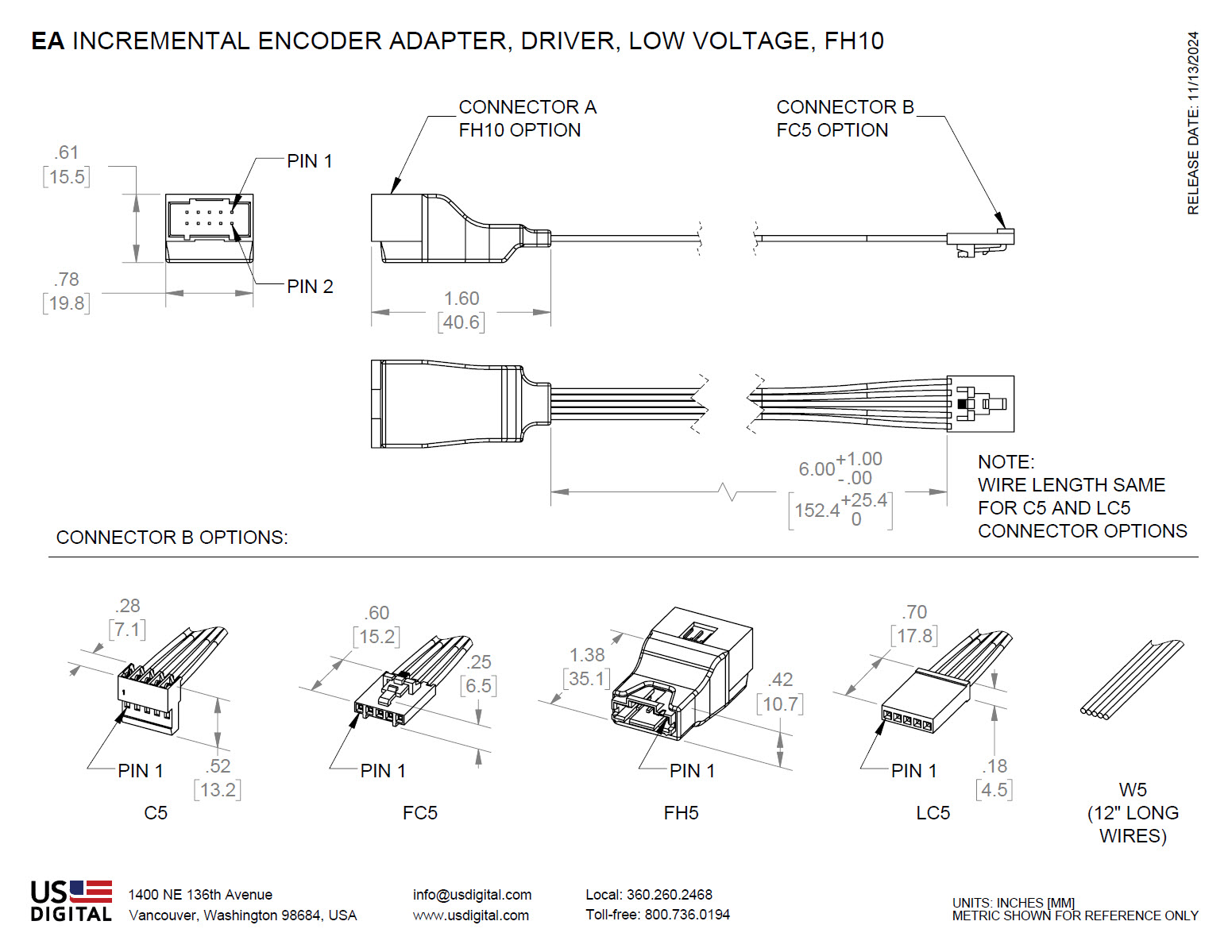
The EA-D-L-10- is a differential RS-422 cable driver which converts the single-ended A/B/I output from USD's single-ended incremental encoders (or any three TTL level digital signals) to 3 pairs of differential signals. This allows the encoder to drive long cables (up to 1000 ft.) and reduces false switching in noisy environments. Various connector options are available on the 5-pin input side of this adapter. The output differential signals are available on a male 10-pin latching connector (FH10). The differential signal from the EA-D-L-10- can be connected directly to US Digital's QSB and USB4 interface products.
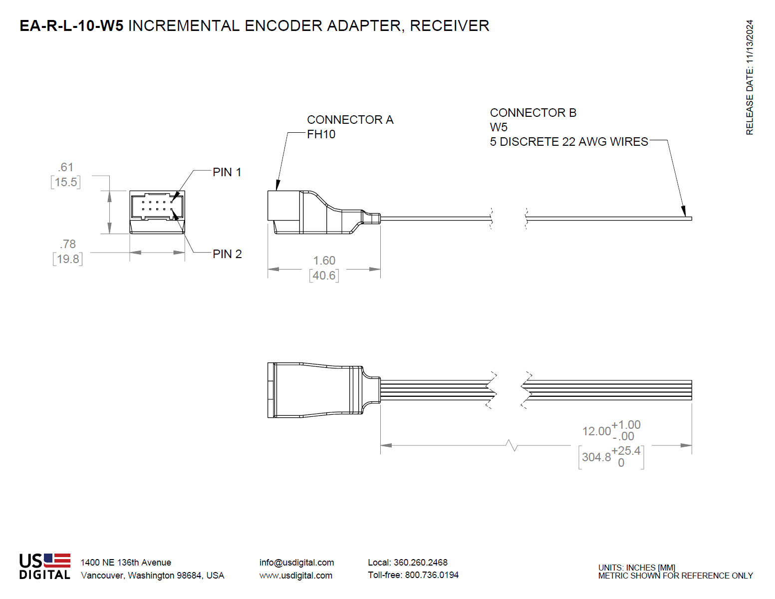
The corresponding receiver, EA-R-L-10-W5 converts the received differential signals back to 3 single-ended TTL level digital signals. The differential input side of the receiver is a 10-pin male latching connector (FH10). The single-ended 5-pin output side has five wires.
Single-ended Cable Driver
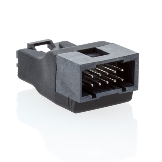
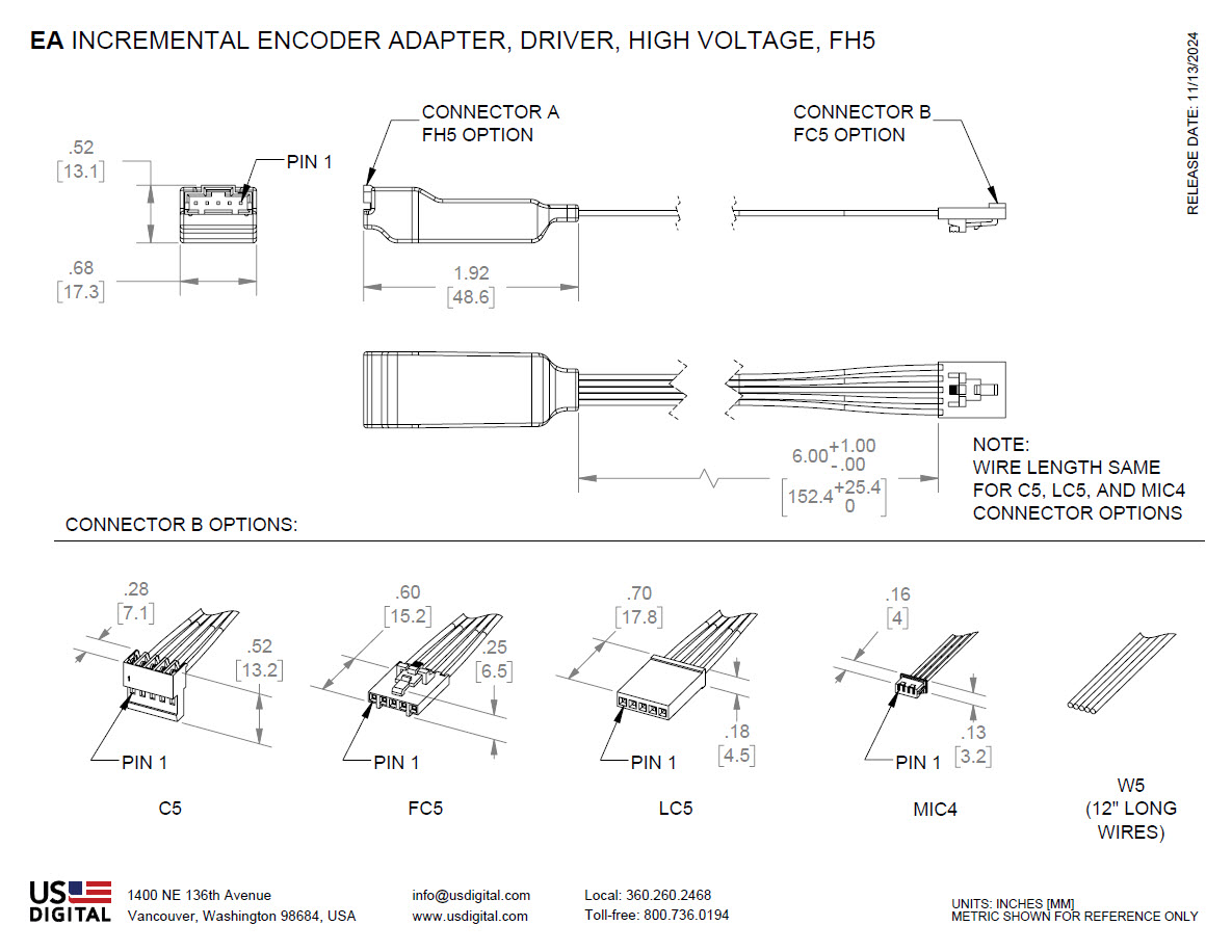
The EA-D-H-5- driver converts the single-ended A/B/I output from USD’s incremental encoders (or any 3 TTL level signals) to 3 digital outputs with a large voltage swing proportional to the power supply voltage. The power supply voltage range is 7.5 to 30VDC. The EA-D-H-5- allows 5V encoders to be used in high voltage applications. The output side of the driver is a 5-pin male latching connector (FH5). Various connector options are available on the 5-pin input side.
US Digital can supply nearly any cable to your specifications. See the Cables & Connectors page for more information.
Mechanical Drawings
Specifications
ENVIRONMENTAL
| PARAMETER | VALUE | UNITS |
|---|---|---|
| Operating Temperature | -40 to 85 | C |
| Electrostatic Discharge, Human Body Model | ± 3 | kV |
EA-D-L-10- DRIVER ELECTRICAL CHARACTERISTICS
| PARAMETER | MIN. | TYP. | MAX. | UNITS | NOTES |
|---|---|---|---|---|---|
| Supply Voltage | 4.5 | 5.5 | Volts | ||
| Supply Current | 4.5 | 9.0 | mA | ||
| Output High Voltage | 2.5 | Volts | I(OH) = -20 mA | ||
| Output Low Voltage | 0.8 | Volts | I(OL) = 20 mA | ||
| Propagation Time | 15 | ns |
EA-D-H-5- DRIVER ELECTRICAL CHARACTERISTICS
| PARAMETER | MIN. | TYP. | MAX. | UNITS | NOTES |
|---|---|---|---|---|---|
| Supply Voltage (Vs) | 7.5 | 30 | Volts | ||
| Encoder Supply Current | 200 | mA | |||
| Propagation Time | 236 | 330 | ns | ||
| Output Low Voltage | 0.5 | Volts | |||
| Output High Voltage | Vs - 2.0 | Volts | |||
| Output Current Source/Sink | 20 | mA |
EA-R-L-10-W5 RECEIVER ELECTRICAL CHARACTERISTICS
| PARAMETER | MIN. | TYP. | MAX. | UNITS | NOTES |
|---|---|---|---|---|---|
| Supply Voltage | 4.5 | 5.5 | Volts | ||
| Supply Current | 16 | 25 | mA | ||
| Input High Voltage | 2.0 | Volts | I(OH) = -20 mA | ||
| Input Low Voltage | 0.8 | Volts | I(OL) = 20 mA | ||
| Propagation Time | 35 | ns |
DRIVER (EA-D-) PINOUT
The driver input is a 4-pin or 5-pin connector. See "Connector B Options" for pictures of the available connectors.
The output connector is a 5-pin latching connector, FH5 (TE # 2-103634-7), or a 10-pin latching connector, FH10 (MOLEX# 74162-2010).
FH5 Output Connector:

FH10 Output Connector:

| PIN | INPUT 4-PIN CONNECTOR (MIC4) | INPUT 5-PIN CONNECTOR (C5, FC5, FH5, LC5, W5) | EA-D-H-5- OUTPUT 5-PIN CONNECTOR (FH5) |
EA-D-L-10- OUTPUT 10-PIN CONNECTOR (FH10) |
|---|---|---|---|---|
| 1 | +5VDC power | Ground | Ground | Ground |
| 2 | A channel (in) | Index (in) | Index (out) | Ground |
| 3 | Ground | A channel (in) | A channel (out) | Index- (out) |
| 4 | B channel (in) | +5VDC power | +7.5 to +30VDC power | Index+ (out) |
| 5 | B channel (in) | B channel (out) | A- channel (out) | |
| 6 | A+ channel (out) | |||
| 7 | +5VDC power | |||
| 8 | +5VDC power | |||
| 9 | B- channel (out) | |||
| 10 | B+ channel (out) |
Notes:
(1) For the EA-D-L-10, the +5VDC pins on the input and output connectors are electrically connected together, so power can be applied to either the input or output connector. For the EA-D-H-5, the 7.5 to 30VDC power is applied at the OUTPUT connector. +5V out is generated at the INPUT connector.
RECEIVER (EA-R-) PINOUT
The receiver input is a 10-pin latching connector, FH10 (MOLEX# 74162-2010). The output has five 12" discrete wires (W5).
FH10 Input Connector
| PIN | INPUT 10-PIN CONNECTOR (FH10) | OUTPUT 5-PIN (W5) |
|---|---|---|
| 1 | Ground | Ground |
| 2 | Ground | Index (out) |
| 3 | Index- (in) | A channel (out) |
| 4 | Index+ (in) | +5VDC power |
| 5 | A- channel (in) | B channel (out) |
| 6 | A+ channel (in) | |
| 7 | +5VDC power | |
| 8 | +5VDC power | |
| 9 | B- channel (in) | |
| 10 | B+ channel (in) |
Notes:
(1) The +5VDC pins on the input and output connectors are electrically connected, so power can be applied to either the input or output.
CONNECTOR B OPTIONS
| OPTION | DESCRIPTION | MANUFACTURER INFO |
|---|---|---|
| C5 | Five 22 AWG 6" discrete wires with a standard connector | TE# 3-640440-5 |
| FC5 | Five 22 AWG 6" discrete wires with a latching connector | MOLEX# 14-56-7052 |
| FH5 | 5-pin latching header | TE# 2-103634-7 |
| LC5 | Five 22 AWG 6" discrete wires with a locking connector | TE# 1-87175-2 (Housing) TE# 87124-1 (Contacts) |
| MIC4 | Four 26 AWG 6" discrete wires with a micro connector | MOLEX# 51021-0400 (Housing) MOLEX# 50079-8000 (Contacts) |
| W5* | Five 22 AWG 12" discrete wires | UL 1061-22/7-3 |
| C5 | FC5 | FH5 |
|---|---|---|
 |
 |
 |
| LC5 | MIC4 | W5* |
|---|---|---|
 |
 |
 |
*Note: The W5 pin-out is as follows:
| PIN | DESCRIPTION | COLOR |
|---|---|---|
| 1 | Ground | Brown |
| 2 | Index | Violet or NC |
| 3 | A channel | Blue |
| 4 | +5VDC power | Orange |
| 5 | B channel | Yellow |
DRIVER VS. RECEIVER

Notes
- US Digital® warrants its products against defects in materials and workmanship for two years. See complete warranty for details.
Configuration Options |
||||||||||||||||||||
| EA | - | Type D (Driver) Connector A: Output Connector B: Input R (Receiver) Connector A: Input Connector B: Output | - | Voltage L (Low Voltage) H (High Voltage) | - | Connector A 5 (FH5) 10 (FH10) | - | Connector B C5 (Inline Version with C5 Connector) FC5 (Inline Version with FC5 Connector) FH5 (FH5 Header) LC5 (Inline Version with LC5 Connector) MIC4 (Inline Version with MIC4 Connector) W5 (12" discrete wires) | ||||||||||||
|
PLEASE NOTE: This chart is for informational use only. Certain product configuration combinations are not available. Visit the EA product page for pricing and additional information. |
||||||||||||||||||||