Glossary of Terms
-
Absolute Encoder
An Absolute Encoder is a device that reports the shaft angle within a 360 deg. range. An absolute encoder does not lose its position after a power-down and provides the absolute position upon power-up without requiring a home cycle or any shaft rotation. A traditional absolute encoder has one track per encoder bit and provides one fixed resolution. Thus, a 1024 position encoder would have 10 tracks (one bit per track). US Digital absolute encoders use a single barcode track that is precisely read by an internal microcontroller or DSP. This enables the resolution, the zero point, and the incrementing direction to be set by nonvolatile configuration parameters in the field.
-
Accuracy
Encoder Accuracy is the difference between the target position and the actual position. It is typically specified in degrees, arcminutes or arcseconds. See white paper and blog with video.
-
Channel
A Channel is an electrical output signal from an incremental encoder. Channels are designated A and B for the two Cquadrature outputs and I or Z for the index output. See Quadrature.
-
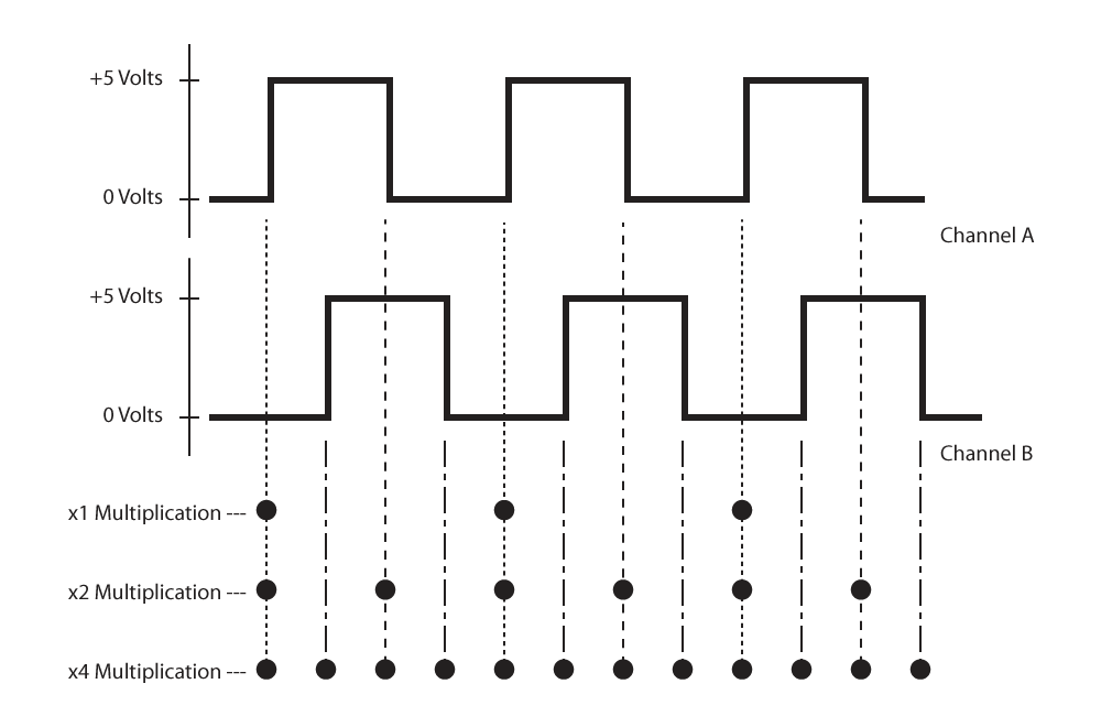
CPR (Cycles Per Revolution)
CPR is the number of full quadrature cycles per full shaft revolution (360 mechanical degrees). A 200 CPR encoder can provide 200, 400, or 800 positions per revolution depending on whether x1, x2, or x4 quadrature decoding is done. See Resolution.
-
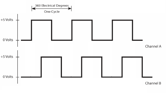
Cycle
A Cycle refers to one complete four-state quadrature cycle. One quadrature cycle is generated by one line and one window called a line pair on the encoder disk.
Each cycle is divided into 360 electrical degrees (°e) and can be decoded into 1, 2, or 4 counts, referred to as x1, x2, or x4 resolution multiplication. See Resolution.
-
Cycle Error
Cycle Error is the difference between the target (theoretical) position of the shaft and the actual position indicated by the encoder cycle count.
-
Differential Output
Differential Output is an output employing a complementary channel for the standard encoder output channels. Each complementary channel provides -5VDC simultaneously as the original channel provides +5VDC. These complementary outputs can be transmitted over much longer distances while maintaining the signal integrity. Differential outputs also help to reduce the effects of electrical noisy environments. Using a differential output does require a differential input or differential receiver to which the other end of the cable is connected. US Digital has several encoders which have a differential line driver option.
-
Disk
A Disk is the round mylar material used by US Digital on which is placed an evenly spaced pattern of windows and lines. When that pattern passes between an LED and detector the encoder provides a corresponding output. The number of line/window pairs provide the native resolution. The disk is also available mounted on an aluminum hub and is called a HubDisk. Disks and HubDisks.
-
Duty Jitter
Duty Jitter is a variation from pulse width to adjacent pulse width.
-
Eccentricity Error
Eccentricity Error is the measurement in the error of a rotary encoder caused by an eccentricity in the mounting of the encoder disk.
-
Electrical Degree (°e)
-
Encoder
An Encoder is an electro-mechanical device that translates physical motion into an electrical signal. That data can be used by a control device to determine speed, acceleration, direction, and position. Encoders can use optical, magnetic, capacitive, or other technologies to detect motion. Encoders can be used for rotary or linear motion and can provide incremental or absolute outputs. Encoders.
-
Encoder Module
An Encoder Module is an electronic component made by US Digital which incorporates an LED and detector through which a medium with evenly spaced lines and windows passes to provide an output which can be used by a control device to determine speed, acceleration, direction, and position. US Digital’s encoder modules are used in many of its encoders. Encoder Modules.
-
Frequency
Frequency is the number of cycles per second which can be read by an encoder. Each encoder is rated at specific frequencies based on how fast the encoder can read the information on a disk. Higher resolutions may reduce the read rate which limits the speed (RPM) at which the encoder is effective.
-
Homing Cycle
A Homing Cycle is the movement of an incremental encoder to find its index. This is helpful upon power-up as without an index and homing cycle, the location within the encoder’s rotation cannot be determined. A homing cycle on a rotary encoder is completed by rotating the shaft until the index is detected. An encoder using this process is sometimes referred to as a Pseudo-Absolute Encoder.
-
HubDisk
A HubDisk assembly consisting of an aluminum hub and an optical encoder disk.
-
Inclinometer
An Inclinometer is a device that reports the angle of an object with respect to gravity. Also known as a "tilt sensor."
-
Incremental Encoder
An Incremental Encoder is made up of 2 major parts: the disk and the sensor. The disk of an incremental encoder is patterned with a single track of repeating identical lines near the outside edge of the disk. The number of line pairs on the disk determines the encoder resolution (CPR). Virtually all incremental encoders produce quadrature outputs that indicate the shaft's speed, angle, and direction. Incremental encoders are commonly used as feedback devices for motor controllers. They also serve as operator interfaces and are sometimes called rotary pulse generators. An operator can turn the knob of a front panel encoder to control a parameter or motor. These are also referred to as "soft" controls since they have no stops, and the limits and control parameters can be set by software rather than hardware. An incremental encoder can serve as a pseudo-absolute encoder by providing a battery backup power supply to the encoder or executing a home cycle after power-up. See Pseudo-Absolute Encoder.
-
Index (Ch. I)
Index (Ch. I), also referred to as the Z-channel. The index channel is normally a once per revolution pulse sent from the encoder. The index channel can use this output to indicate a zero or home position on the encoder. The index outputs of US Digital encoders are internally gated to coincide with the low states of channels A and B. This provides a precise index position that is 1/4 of one quadrature cycle wide. Normally, the index output goes high once per revolution. US Digital can make custom disks to provide multiple indexes per revolution. Adding an index channel to an incremental encoder allows the encoder to provide absolute position. See Home Cycle.
-
Interpolation
Interpolation is the internal multiplication of a signal in an encoder providing a higher resolution than the native disk resolution. This is executed via the internal circuitry in an encoder or encoder module. The stated CPR of the encoder includes any interpolated multiplication.
-
IP (Ingress Protection) Ratings
IP Ratings identify the ability of an enclosure to resist intrusion. Common examples are IP64 and IP69. The first digit indicates the protection against the ingress of solids (eg. dust) and the second digit indicates the protection against the intrusion of liquids (eg. Water). The higher the number, the better the protection.
-
Line Count
Line Count is the number of equally spaced lines on a linear strip or disk. The space between each line is referred to as a window. Each line/window pair is the basis for creating each electrical cycle as the disk turns. The line count for a rotary disk is stated in CPR (cycles per revolution) while it is stated in LPI (lines per inch) on a linear strip.
-
Line Driver
A Line Driver is a circuit designed to increase the maximum recommended cable length for an encoder, and/or to add immunity from electrical noise or interference on the signal lines. US Digital has a differential output option available on some of its encoders.
-
Linear Strip
A Linear Strip is the mylar material used by US Digital on which is placed an evenly spaced pattern of windows and lines. When that pattern passes between an LED and detector the encoder provides a corresponding output. The number of line/window pairs provide the native resolution.
-
Moment of Inertia
The Moment of Inertia is the point at which the rotational force being applied to a shaft equals the resistance to change in angular velocity.
-
Magnetic Encoder
A Magnetic Encoder is an encoder that uses code wheels with alternating magnetic poles or unique patterns distributed around the wheel. A magnetic sensor in the encoder detects the change in the magnetic field as the wheel rotates and produces a digital pulse train.. See MAE3, MA3, and M3K. Also see Optical Encoders
-
Noise
Noise is any unwanted electrical signal that can potentially interfere with a desired signal. The potential sources for electrical noise are numerous. Electrical noise can be mitigated by using a differential output or by shielding the desired signal. See Differential Output.
-
Open Collector Output
Open Collector Output is an output that allows the user to set the voltage level of the output signal by installing a pull-up resistor between the output channel and a power supply of the desired voltage.
-
Optical Encoder
An Optical Encoder is an encoder using a light source, detector and interrupting medium to provide an output based on the speed and direction of the lines on that medium. Optical encoders can be transmissive—often with the light on one side of the medium and the detector on the other side or they can be reflective—the detector seeing the light reflected off of the patterned disk. Read more...
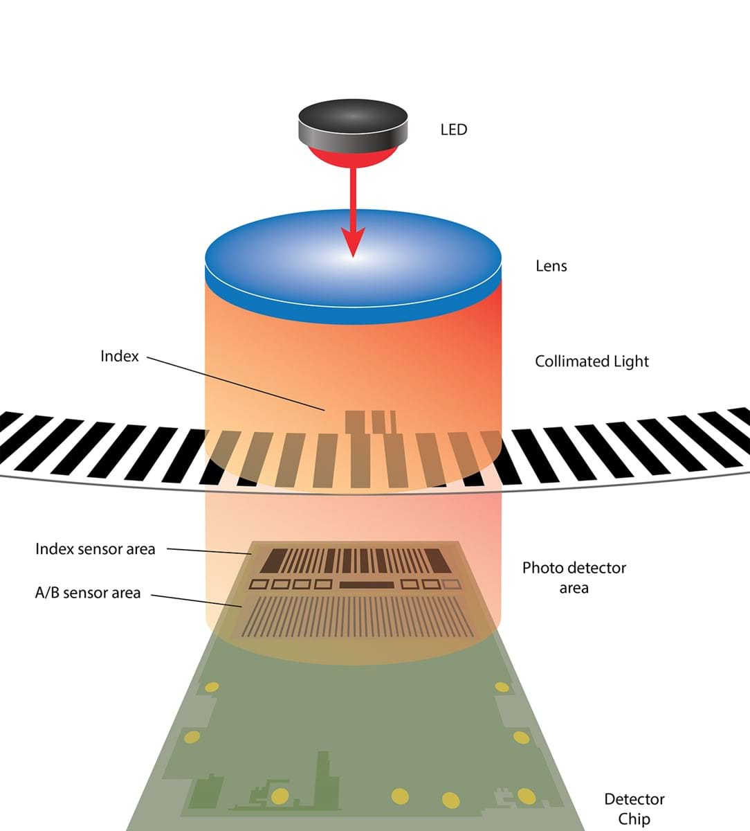
The interrupting medium is a disk for rotary encoders and a linear strip for linear encoders. The output is dependent on the quality of the pattern on the disk or strip. US Digital makes the code wheels for all of our encoders. The code wheel patterns are created using precision digital plotters and cut using a precision laser cutter. US Digital uses a highly collimated solid-state light source. Most of US Digital’s optical encoders are transmissive. The collimated light rays pass through the disk (or strip) pattern. The image of the pattern is detected using a phased array monolithic sensor and is converted to TTL digital quadrature outputs. Reflective type encoders (E4T / S4T) bounce the collimated light off a patterned reflective code wheel. This means all of the electronics are one side of the code wheel making for a more compact design. See Magnetic Encoder
-
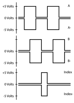
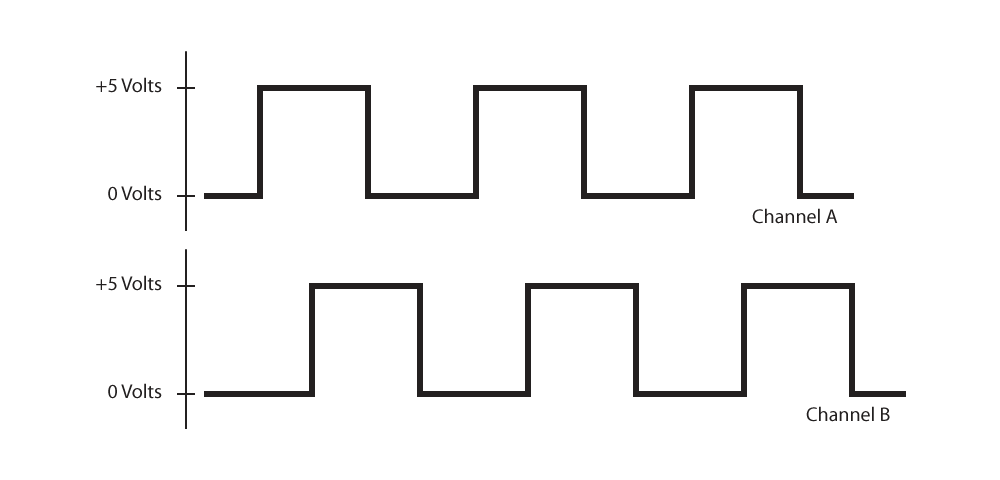
Output Waveforms
Output Waveforms are the relationship of the output signals to each other, normally shown in a diagram as below. This shows the sequence of all output signals including channels A, B, and Z as well as their inverse signals for differential output encoders.

-
Phase
A Phase the delay in time or degrees between the rising edge of channel A and the rising edge of channel B. Also defined as the delay between the center of the high state on channel A to the center of the high state on channel B.
-
Phased Array
A Phased Array is a pattern of photodiodes used on US Digital encoders to detect several lines and windows simultaneously. The array averages these pairs to provide an output that is more consistent than those using fewer sensors. In US Digital’s design, there are also two photodiodes for every line and window. The phased array allows for a wider gap tolerance and excellent tolerance to some disk contamination.
-
Phase Jitter
Phase jitter is the variation between the rising edges of channel A and channel B from one cycle to another.
-
Phase Relationship
Phase Relationship identifies which channel (A or B) leads (goes high first) the other channel based on the rotation of the shaft. The perspective from which the relationship is viewed is also included in this specification.
-
Position Error
See Cycle Error
-
PPR (Pulses Per Revolution)
PPR is the term US Digital uses to refer to the number of pulses after 4x quadrature multiplication. US Digital uses CPR to identify the before quadrature resolution of an encoder. (Note: Some vendors of encoders use the same acronyms of CPR and PPR with differing definitions.)
-
Pseudo-Absolute Encoder
A Pseudo-Absolute Encoder is an incremental encoder used as an absolute encoder on single turn applications which use a homing cycle. This requires that the media (disk or linear strip) include an index. On power-up, the system performs a homing cycle, moving until the index is detected. At that point the exact position is determined. To reduce the amount of movement required to find the index, the media can use more than one index with a unique number of line/window pairs between the indices. During the homing cycle, as soon as the second index is located, the exact position is determined.
-
Quadrature
Quadrature is the most common digital incremental encoder output. It uses two channels (typically referred to as channels A and B) which are offset from each other by 90 electrical degrees. This output enables one to determine the direction of movement (by viewing which channel is leading the other) and allows for resolution multiplication—providing up to four times the CPR resolution.
-
Resolution
Resolution relates to the quantity of increments an encoder has in one rotation (for a rotary encoder). An encoder disk has a specified number of lines on it providing for a native resolution equal to the number of line/window pairs on the disk. Resolution can be increased via interpolation, multiplying the native resolution by any number of times. This output, either native or interpolated is the encoder resolution which US Digital refers to as the CPR—cycles per revolution. Using two channels (A & B) of a quadrature encoder enables the output of the encoder to be decoded up to four times the native or interpolated encoder output. US Digital refers to that special decoding as PPR standing for Pulses Per Revolution.
-
Revolution
Revolution is one complete rotation of the encoder shaft, 360 mechanical degrees.
-
Shaft Axial Play
Shaft Axial Play is the movement of the shaft in the axial direction. US Digital states the maximum shaft axial play in thousandths of an inch.
-
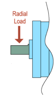
Shaft Loading aka Radial Load
Shaft Loading is the specification used on shafted encoders and refers to the force applied perpendicular to the shaft. An increase in the amount of force on a shaft will decrease the bearing life. Use the formula provided on the datasheet for shafted encoders.
-
Shaft Runout
Shaft Runout is the deviation of a shaft from true circular rotation. This can be caused by a bent shaft or a loose bearing. US Digital’s datasheets for encoder kits have a rating of TIR—Total Indicated Runout and is specified in thousandths of an inch. If an encoder is installed onto a shaft exceeding those specifications, the output of the encoder can be unreliable.
-
Single-Ended Output
Single-Ended Output is the most basic kind of output on an encoder. Each channel only has one wire which provides a train of pulses alternating between 0 to 5 volts in relationship to ground. While it is the most common, it is inherently susceptible to electrical noise and the length of the cable is quite limited. Using a differential output will resolve both of those issues.
-
Stiction
Stiction is a combination of the words stick and friction. Stiction exists when the static (starting) friction exceeds the dynamic (moving) friction. An example of stiction would be a shaft sticking when small changes are attempted, requiring a larger input force to initiate movement. The result is that the force required to start the shaft moving is more than what is needed to go to the desired shaft position, causing the movement to be jerky.
-
Symmetry
Symmetry is the relationship of the on time to the off time (x,y) for any encoder channel. This specification is shown on the datasheet in electrical degrees for the EM1 and the EM2 encoder modules.

-
TIR (Total Indicated Runout)
TIR is a measurement of shaft runout—deviation of a shaft from true circular rotation.