US Digital

E5 Optical Kit Encoder

1 / 3

Overview

  • Quick, simple assembly and disassembly
  • Rugged screw-together housing
  • Positive finger-latching connector
  • Accepts .010" axial shaft play
  • 32 to 1250 cycles per revolution (CPR)
  • 128 to 5000 pulses per revolution (PPR)
  • 2 channel quadrature TTL squarewave outputs
  • Optional index (3rd channel)
  • -40 to +100C operating temperature
  • Mounting compatibility with Agilent HEDS-5500

The E5 Series rotary encoder has a molded polycarbonate enclosure with either a 5-pin or 10-pin finger-latching connector. This optical incremental encoder is...

Read more

Product Specifications

ParameterDimensionUnits
Moment of Inertia 8.0 x 10^-6 oz-in-s²
Hub Set Screw 3-48 or 4-48 in.
Hex Wrench Size .050 in.
Encoder Base Plate Thickness .135 in.
3 Mounting Screw Size 0-80 in.
2 Mounting Screw Size 2-56 or 4-40 in.
3 Screw Bolt Circle Diameter .823 ±.005 in.
2 Screw Bolt Circle Diameter .750 ±.005 in.
Required Shaft Length .445 to .570* in.
With E-option .445 to .750* in.
With H-option >=.445* in.
Single-ended (S-option) Weight 0.82 oz.
Differential (D-option, L-option) Weight 0.91 oz.

* Add .125" to the required shaft length when using R-option.

ParameterMax.Units
Vibration (5 to 2kHz) 20 g
Shaft Axial Play ±0.010 in.
Shaft Eccentricity Plus Radial Play 0.004 in.
Acceleration 250,000 rad/sec²
Maximum RPM
e.x. CPR = 1250, max. rpm = 4800
e.x. CPR = 512, max. rpm = 11718
e.x. CPR = 50, max. rpm = 60000
e.e. CPR = 32, max. rpm = 60000
minimum value of (6000000 / CPR) and (60000) rpm
  • Note that radial play translates directly to position inaccuracy.
  • Note: 60000 rpm is the maximum rpm due to mechanical considerations. The maximum rpm due to the module's 100kHz maximum count frequency is (6000000/CPR).

A leads B for clockwise shaft rotation, and B leads A for counterclockwise rotation viewed from the cover/label side of the encoder (see the EM1 / HEDS page).

  • Specifications apply over entire operating temperature range.
  • Typical values are specified at Vcc = 5.0Vdc and 25°C.
  • For complete details see the EM1 and HEDS product pages.
  Supply Current Output voltage low Output voltage high 
Resolution Typ / Max Max Min Based on
50,96, 100, 110, 120, 192, 200, 250, 256, 360, 400, 500, 512, 540 CPR, non-index 17 / 40 mA 0.4 volts @ 3.2mA 2.4 volts @ -200uA Low-res HEDS
1000, 1016, 1024 CPR, non-index 57 / 85 mA 0.5 volts @ 8mA 2.4 volts @ -40uA High-res HEDS
32 CPR, with index 27 / 30 mA 0.5 volts @ 8mA 2.0 volts @ -8mA EM1
50,96, 100, 192, 200, 250, 256, 360, 400, 500, 512 CPR, with index 57 / 85 mA 0.5 volts @ 8mA 2.4 volts @ -40uA High-res HEDS
720, 900, 1000, 1024, 1250 CPR, with index 55 / 57 mA 0.5 volts @ 8mA 2.0 volts @ -8mA EM1
Specification Min. Typ. Max. Units Notes
Supply 4.5 5.0 5.5 Volts  
Current Consumption
Index: 32 CPR   28 53 mA No load
Index: 720, 720, 900, 1250 CPR   56 59 mA No load
Index: All Other Resolutions   58 88 mA No load
Non-index: <2000 CPR   18 43 mA No load
Non-index: >=2000   58 88 mA No load
Output Voltage
Sourcing to +5 2.4 3.5   Volts @ - 20mA
Sinking to Ground   0.2 0.4 Volts @ 20mA
Parameter Torque
Hub Set Screw to Shaft 2-3 in.-lbs.
Cover (4-40 screws through cover into base) 2-3 in.-lbs.
Base to Mounting Surface 4-6 in.-lbs.
Base to Mounting Adapter Plate 4-6 in.-lbs.
Adapter Plate to Mounting Surface 4-6 in.-lbs.

Be sure to keep different diameters, resolutions and options separated. The resolution of the optoelectronic modules and the code wheels must match. Index and non-index parts cannot be mixed since the optical patterns are different. An identifier is stamped on each optoelectronic module.

For Agilent Modules (HEDS):

The 2-channel (non-index) version can be identified by a 9100 or 9200. The 3-channel (index) version can be identified by a 9140. One letter specifies the resolution as shown in the table below.

For US Digital Modules (EM1):

Only available in 3-channel (index) version and are identified by a 1 for 1" disk. The second number indentifies the resolution as shown in the table below (in italics).

Disk Standard Index
32 - 1-32
50 S S
96 C C
100 C C
110 C -
120 C -
192 E E
200 E E
250 F F
256 F F
360 G G
400 H H
500 A A
512 I I
540 I -
720 - 1-720
900 - 1-900
1000 B 1-1000
1016 J -
1024 J 1-1024
1250 - 1-1250

Index

Provides a single pulse per revolution.

3-option

The 3-option makes all five of these hole diameters .125". The .438" diameter center hole can also mate with a motor boss.

View option:

S-3-option.jpg


 D-3-option.jpg


A-option

The A-option adds a .497" diameter alignment shoulder designed to slip into a .500" diameter recess in the mounting surface centered around the shaft.

View option:

S-A-option.jpg

D-A-option.jpg

E-option

The E-option provides a cylindrical extention to the cover allowing for longer shafts of up to .750".

View option:

S-E-option_0.jpg

D-E-option_0.jpg

G-option

This option includes molded ears on the E5 base which enable it to be mounted to a 1.812" diameter bolt circle. The mounting holes are designed to fit 4-40 screws. Because the ears are molded to the E5 base this does not increase the thickness of the encoder and does not add to the required shaft length. This option will work with shaft lengths of .445" to .570".

View option:

S-G-option.jpg

D-G-option.jpg

H-option

The H-option adds a hole to the cover for the shaft to pass through.

  • Shafts 2mm to 4mm, a .203" diameter hole is supplied.
  • Shafts 3/16" to 1/4", a .295" diameter hole is supplied.
  • Shafts 5/16" to 10mm, a .438" diameter hole is supplied.
View option:

S-H-option.jpg

D-H-option.jpg

L-option

Provides Avago / Agilent / HP compatible pin-out.

Please note: Only available for E5D and E5MD (differential versions).

R-option

This adapter is an 1/8" thick fiberglass adapter which is pre-mounted to the base of the encoder. It allows the E5 to be rotated 15 while operating for index orientation. Use three 4-40 x 1/4" screws (sold separately). When installing the hub, rotate the index to the approximate position. After assembly, with the 3 screws loose, rotate while operating to the desired index location and tighten. Note that this adds 1/8" to the required shaft length. Please note: Only available in polycarbonate versions (E5D and E5S).

View option:

S-R-option.jpg

D-R-option.jpg

T-option

When mounting holes are not available, a pre-applied transfer adhesive (with peel-off backing) is available for stick-on mounting. Use the centering tool (sold separately) to slide the base into position. T-option specifies transfer adhesive on the standard mounting base. Please note: Only available in polycarbonate versions (E5D and E5S).

S-T-option.jpg

D-T-option.jpg

Centering Tools

Part #: CTOOL - (Shaft Diameter)

Description: This reusable tool provides a simple method for accurately centering the E5 base onto the shaft. It is recommended for the following situations:

  • When using mounting screws smaller than 4-40.
  • When the position of the mounting holes is in question.
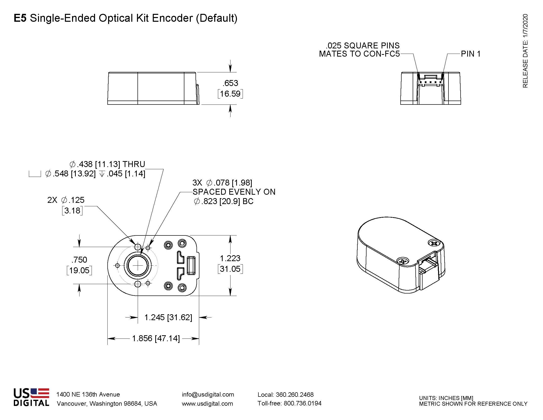
  • When using the 3-hole mounting pattern.
  • When using the T - option transfer adhesive.

Instructions: When mounting encoder base, slide centering tool down shaft until it slips into centering hole of encoder base. Tighten mounting screws, then remove centering tool.

Hex Tools

Part #: HEXD-050 (only included with default or PKG1 - packaging options).

Description: Hex driver, .050" flat-to-flat for 3-48 or 4-48 set screws.

Part #: HEXW-050 (only included with PKG2 or PKG3 - packaging options).

Description:  Hex wrench, .050" flat-to-flat for 3-48 or 4-48 set screws.

Spacer Tools

Part #: SPACER-4218

Screws

Part #: SCREW-080-250-PH

Description: Pan Head, Cross Drive 0-80 UNF x 1/4"

Quantity Required for Mounting: 3 per encoder

Part #: SCREW-256-250-PH

Description: Pan Head, Cross Drive 2-56 UNC x 1/4"

Quantity Required for Mounting: 2 per encoder

Part #: SCREW-440-250-PH

Description: Pan Head, Cross Drive 4-40 UNC x 1/4"

Quantity Required for Mounting: 2 per encoder

5-pin Single-Ended 10-pin Differential Standard 10-pin Differential (L-option*)
Pin Description Pin Description Pin Description
1 Ground 1 Ground 1 No Connection
2 Index 2 Ground 2 +5VDC power
3 A channel 3 Index- 3 Ground
4 +5VDC power 4 Index+ 4 No connection
5 B channel 5 A- channel 5 A- channel
    6 A+ channel 6 A+ channel
    7 +5VDC power 7 B- channel
    8 +5VDC power 8 B+ channel
    9 B- channel 9 Index-
    10 B+ channel 10 Index+

* Avago / Agilent / HP compatible version.

View the PDF version of this document.

Please note:
  • Shown using Polycarbonate Single-ended version.
  • These instructions are compatible for all versions of the E5.
  • step1_5.gif
    1. Base Mounting

    Secure base to mounting surface using two or three screws. If a centering tool is used, slip it over shaft and into center hole of base. Tighten mounting screws. Remove centering tool.


  • step2_2.gif
    2. Spacer Installation

    Place spacer tool around shaft as shown.


  • step3_4.gif
    3. Codewheel Installation

    Slip codewheel over shaft with mylar disk towards top until it bottoms out against spacer tool. Tighten set screw with hex wrench provided while pressing down on hub.


  • step4a_1.gif
    4. Encoder Module Installation

    Slip optical module into position until the two alignment pins slip into holes of module (thick side of module towards bottom). Secure with 4-40 x 1/2" screws (supplied).


  • step5_1.gif
    5. Cover Installation

    Place housing (cover) over assembly and secure with two 4-40 x 5/8" cover screws (supplied).

Product Description

Restriction of Hazardous Substances

The E5 Series rotary encoder has a molded polycarbonate enclosure with either a 5-pin or 10-pin finger-latching connector. This optical incremental encoder is designed to easily mount to and dismount from an existing shaft to provide digital feedback information.

The E5 Series is easy to add to existing applications and only consists of five main components: base, cover, hub/code wheel, optical encoder module and internal differential line driver (differential version only).

The single-ended output version (S-option) is typically used with cables of 6 feet or less. For longer cable lengths, the differential output version (D-option) is recommended.

The base and cover are both constructed of a rugged 20% glass filled polycarbonate . Attachment of the base to a surface may be accomplished by utilizing one of several machine screw bolt circle options. Positioning of the base to the centerline of a shaft is ensured by use of a centering tool (sold separately). The cover is securely attached to the base with two 4-40 flat head screws to provide a resilient package protecting the internal components.

The internal components consist of a shatterproof mylar disk mounted to a precision machined aluminum hub and an encoder module. The module consists of a highly collimated solid state light source and monolithic phased array sensor, which together provide a system extremely tolerant to mechanical misalignments.

For differential versions: the internal differential line driver (26C31) can source and sink 20mA at TTL levels. The recommended receiver is industry standard 26C32. Maximum noise immunity is achieved when the differential receiver is terminated with a 110-ohm resistor in series with a .0047 microfarad capacitor placed across each differential pair. The capacitor simply conserves power; otherwise power consumption would increase by approximately 20mA per pair, or 60mA for 3 pairs.

A secure connection to the E5 Series encoder is made through a 5-pin (single-ended versions) or 10-pin (differential versions) finger-latching connector (sold separately). The mating connectors are available from US Digital with several cable options and lengths.


Product Notes
  • Cables and connectors are not included and must be ordered separately.
  • US Digital warrants its products against defects in materials and workmanship for two years. See complete warranty for details.

Purchasing

Configure and Purchase

1. CPR
2. Bore
3. Index


4. Output


5. Cover


6. Base


7. Packaging


Product Part Number


Quantity Price
1 $62.32
10 $52.14
50 $43.11
100 $37.47
Over 100 Call for quote
Quantity
Unit Price

$62.32

Subtotal

$62.32


For your convenience, use the above part number to order via phone 800.736.0194

Related Products & Accessories