E4T Product Description

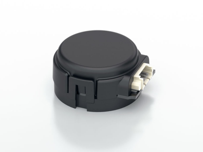
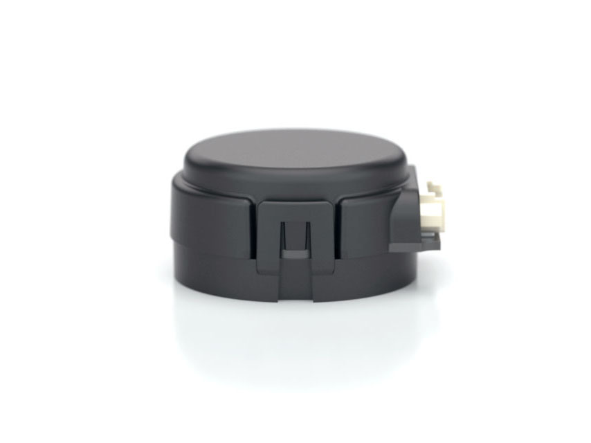
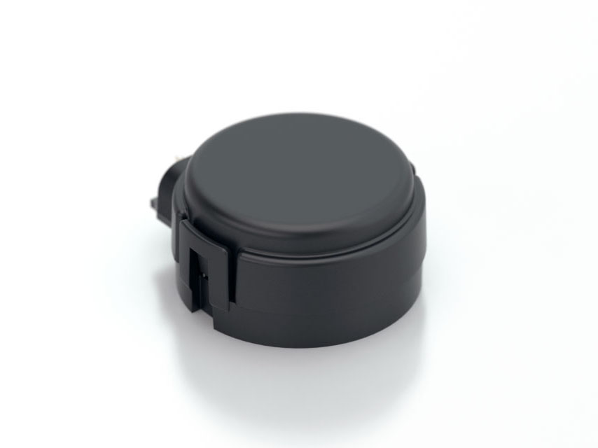
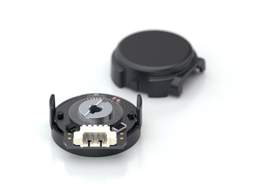
The E4T miniature transmissive optical encoder is designed to provide digital quadrature encoder feedback for high volume, limited space applications. The E4T is designed to be a drop-in replacement for the E4P and offers higher maximum speed and increased output drive. The E4T utilizes an innovative, push-on encoder disk that accepts shaft diameters of 2.0mm to .250 in.
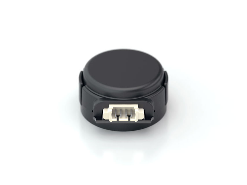
The single-ended output version is connected using a 4-conductor, high retention, polarized, 1.25mm pitch connector. The differential output version uses a similar 6-pin connector. Mating cables and connectors (see the Cables/Connectors web page) are not included and are available separately.
Please Note: Due to the E4T's push-on hub design, it is recommended for use as a one-time installation.
Product Specifications
View here or download the specifications
Environmental
| PARAMETER |
VALUE |
UNITS |
| Operating Temperature |
-20 to 100 |
C |
Electrostatic Discharge, IEC 61000-4-2
Single-ended (-S option)
Differential (-D option) |
± 12
± 7 |
kV |
| Vibration (10Hz to 2kHz, sinusoidal) |
20 |
G |
| Shock (6 milliseconds, half-sine) |
75 |
G |
Mechanical
| PARAMETER |
VALUE |
UNITS |
| Max. Shaft Axial Play |
± .010 |
in. |
| Max. Shaft Runout (TIR) |
.002 |
in. |
| Max. Acceleration |
250,000 |
rad/sec² |
|
Maximum RPM (1)
Maximum A/B Frequency
e.x. CPR = 200, Max. RPM = 30000 |
minimum value of
((6 x 10^6)/CPR)
and (60000)
100
|
RPM
kHz
|
| Max. Codewheel Moment of Inertia |
5.1 x 10^-7 |
oz-in-s² |
Mounting Screw Size
Default (D-option base)
Metric (M-option base) |
#3-48 x 3/16"
M2.5, length 4mm |
|
| Screw Bolt Circle Diameter |
.586 ±.005 |
in. |
| Minimum Shaft Length (2) |
.275 |
in. |
| Maximum Shaft Length (2) |
.395 (D option) /
no limit (H option) |
in. |
| Mounting Screw Torque |
2-3 |
in-lbs |
| Technical Bulletin TB1001 - Shaft and Bore Tolerances |
Download |
(1) 60000 RPM is the maximum rpm due to mechanical considerations. The maximum RPM due to the module's maximum frequency response is dependent upon the module’s resolution (CPR).
(2) Including axial play.
Single-Ended Electrical
| SPECIFICATIONS |
MIN. |
TYP. |
MAX. |
UNITS |
NOTES |
| Supply Voltage |
4.5 |
5.0 |
5.5 |
V |
|
| Supply Current |
|
25 |
30 |
mA |
CPR ≤ 500, no load |
| |
34 |
42 |
mA |
CPR > 500, no load |
| Low-level Output |
|
|
0.4 |
V |
CPR ≤ 500, IOL= 8 mA |
| CPR > 500, IOL= 5 mA |
| |
0.035 |
|
V |
no load |
| High-level Output |
2.4 |
|
|
V |
CPR ≤ 500, IOH= -8 mA |
| CPR > 500, IOH= -5 mA |
| |
4.0 |
|
V |
no load |
| Output Rise Time |
|
100 |
|
ns |
no load |
| Output Fall Time |
|
50 |
|
ns |
no load |
Differential Electrical
| SPECIFICATIONS |
MIN. |
TYP. |
MAX. |
UNITS |
NOTES |
| Supply Voltage |
4.5 |
5.0 |
5.5 |
V |
|
| Supply Current |
|
27 |
32 |
mA |
CPR ≤ 500, no load |
| |
36 |
44 |
mA |
CPR > 500, no load |
| Single-Ended Output Voltage High |
4.75 |
5.0 |
|
V |
Min. @ 25mA load, Typ. @ no load |
| Single-Ended Output Voltage Low |
|
0.25 |
0.60 |
V |
Typ. @ no load, Max. @ 4.5mA load |
| Differential Output Voltage |
3.0 |
3.8 |
|
V |
RL = 100 ohm |
| Differential Output Rise/Fall Time |
|
|
20 |
ns |
|
Phase Relationship

| PARAMETER |
MIN. |
TYP. |
MAX. |
UNITS |
| Symmetry, S |
105 |
180 |
255 |
electrical degrees |
| Quadrature Delay, Q |
30 |
90 |
150 |
electrical degrees |
(1) A leads B for clockwise shaft rotation, B leads A for counter clockwise shaft rotation viewed from the cover side of the encoder.
(2) Typical values represent the encoder performance at typical mounting alignment, whereas the maximum values represent the encoder performance across the range of recommended mounting tolerance.
Pin-Out
| 4-PIN SINGLE-ENDED (1) |
6-PIN DIFFERENTIAL (2) |
| Pin |
Description |
Pin |
Description |
| 1 |
+5VDC power |
1 |
Ground |
| 2 |
A channel |
2 |
A channel |
| 3 |
Ground |
3 |
A- channel |
| 4 |
B channel |
4 |
+5VDC power |
| |
|
5 |
B channel |
| |
|
6 |
B- channel |
(1) 4-pin single-ended mating connector is CON-MIC4
(2) 6-pin differential mating connector is CON-MIC6
Options
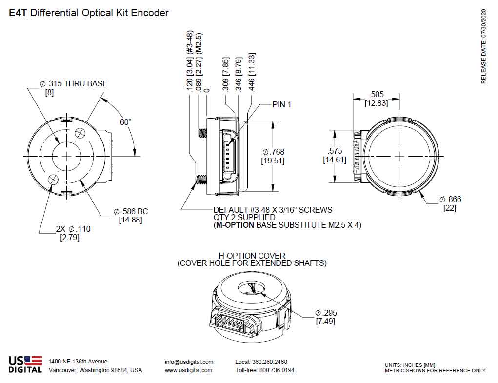
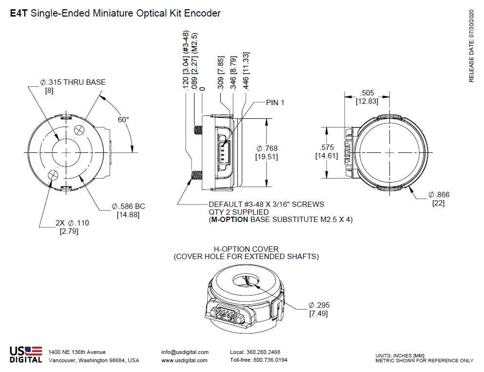
H-OPTION (HOLE IN COVER)
The H-option adds a 0.295" diameter hole in the cover for the shaft to pass through.
M-OPTION (METRIC MOUNTING SCREWS)
Provides alternate metric M2.5, length 4mm screws. When M-option is NOT specified the default is #3-48 x 3/16" screws.
Accessories
1. Centering Tool*
Part #: MCTOOL - (Shaft Diameter)
Description: This reusable tool is used to accurately center the E4T base on the shaft.
2. Spacer Tool*
Part #: SPACER-E4T
Description: This reusable tool is used to properly space the codewheel from the encoder.
*Both the MCTOOL and SPACER-E4T tools are included with all packaging options.
3. Screws
Part #: SCREW-348-188-PH
Description: Pan Head, Philips #3-48 UNC x 3/16"
Use: Base Mounting
Quantity Required: 2
Screws are included with default base option
Part #: SCREW-M25-4MM-BH
Description: Button Head Cap, M2.5 x 0.45 x 4mm
Use: Base Mounting
Quantity Required: 2
Screws are included with metric base option
Product Change Notifications
| Title |
Date |
Description |
Download |
| E4T and S4T Cover and Base Update - PCN 7192 |
3/3/2022 |
As part of our ongoing continuous improvement efforts, and to avoid any potential disruption to our supply chain, US Digital has decided to standardize our plastic material. Based on this, the E4T and S4T encoder cover and base will change from PBT (Polybutylene Terephthalate) to PC (polycarbonate). |
Download |
| E4T, E8T Packaging - PCN 7195 |
2/15/2022 |
As part of our ongoing continuous improvement efforts, US Digital is implementing a change to our packaging options for our E4T and E8T kit encoders. |
Download |
| Updated PCB for E4T and S4T - PCN 6466 |
1/29/2018 |
This notice is to inform our customers of a PCB design change that is being implemented for all of the E4T and S4T product lines. The new PCBs will improve overall product performance and enhance robustness of these product lines. The new PCBs can be identified by their blue color (instead of black) and have two mounting holes that mate with the base plate instead of one hole and one slot. This change has no impact on form, fit or function for either the E4T or S4T. |
Download |
| E4T, S4T and E8T Laser Markings - PCN 6227 |
8/8/2017 |
This notification is to inform our customers of a change to product markings for the E4T, E8T, and S4T series of encoders. The new marking will be utilized across all three product lines. We are making this change to improve readability for our customers and to provide consistency across the product lines. |
Download |
Additional Information
Product Notes
-
Cables and connectors are not included and must be ordered separately.
-
US Digital® warrants its products against defects in materials and workmanship for two years. See complete warranty for details.
Datasheets
Assembly Instructions
Product Change Notifications
Press Releases
3D Model Downloads
Please
configure your product first
to download a 3D model.
(Note: The formats below will become links if there are 3D models available.)
-
SolidWorks Format
-
IGES Format
-
Parasolid Format
-
STEP Format
Product Configurator
Our products are not currently available for direct online purchase. To place an order please contact us directly with your part number.
For purchasing or volume discounts, please configure the part above, then use the completed part number and contact us!
Feedback
US Digital's mission is a commitment to quality and constant improvement. If you find an error to a product on this page, please let us know!