EDAC2 Product Description
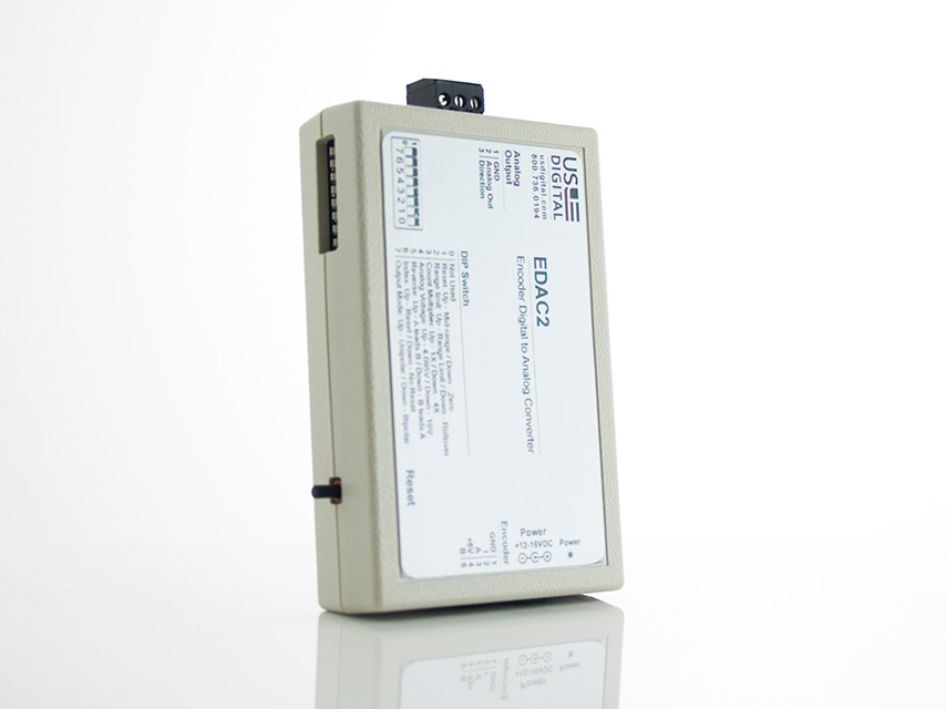
The EDAC2 converts the A and B quadrature output of an incremental encoder into a proportional voltage proportional to the encoder position. The output from the encoder causes an internal 12-bit counter to count up or down. The output of the counter is fed into a 12-bit DAC that converts the 12-bit position count value to an analog voltage.
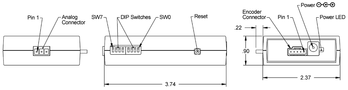
Eight DIP switches are provided to select various options. The user can choose unipolar output mode with 0 to 4.095V or 0 to 10V output, bipolar output mode with ±4.095V or ±10V output, 1X or 4X counting, reset index, reverse rotation, midrange reset, and range limit counting. Full-scale output in 10V mode is actually 9.962V.
The EDAC2 has an internal counter that you may reset in three ways: by pressing the reset button, power cycling the unit, or enabling the reset on the encoder index. The reset may be configured to either mid-range or zero volts.
The EDAC2 also provides a TTL logic level output bit, which changes the state to indicate the analog voltage output's polarity.
Power is provided by an external power supply that provides +5VDC to an external encoder through the encoder input connector. A three-position screw terminal block provides the analog output connections and logic level direction bit output.
Product Specifications
ELECTRICAL
Unless otherwise specified, all accuracy measurements assume operation within temperature range 0C to 70C.
PARAMETER
MIN.
TYP.
MAX.
UNITS
NOTES
Voltage Out to Encoder
4.8
5.0
5.2
Volts
Under 100mA load
Input Supply Voltage
12
-
16
Volts
Supply Current
-
110
-
mA
12V input, no encoder load
Full Scale Output Error - Analog Output
-0.5
0.25
0.5
% full scale
0 - 4.095V output range
Integral Non-linearity Error - Analog Output
-3.0
±1.0
3.0
mV
0 - 4.095V output range
Offset Error - Analog Output
-6.0
±1.0
6.0
mV
0 - 4.095V output range
Quadrature Encoder Inputs*
Polarity Bit Output
Analog Output Load Impedance
2000
-
-
Ohms
* Diode clamped to ground and +5V, 5kΩ pullup to +5V.
ABSOLUTE MAXIMUM RATINGS
PARAMETER
MIN.
TYP.
MAX.
UNITS
Operating Temperature
0
-
70
C
Encoder Current*
0
-
250
mA
Quadrature Input Frequency
0
-
400
kHz
Analog Output Update Frequency
0
-
400
kHz
* +5VDC power for external encoder.
DIP SWITCHES
The EDAC2 is programmed by eight DIP switches in either an up or down position.
SWITCH
NAME
UP ↑
DOWN ↓
EXPLANATION
0
Not Used
-
-
-
1
Reset
Mid-range
Zero
Reset voltage level
2
Range Limit
Range Limit
Rollover
Sets counting mode
3
Count Multiplier
1X
4X
Enables quadrature counting
4
Analog Voltage
4.095V
10V
Sets full scale output voltage
5
Reverse
A / B
B / A
Swaps increasing count direction
6
Index
Reset
No Reset
Ignores the index or resets on index
7
Output Mode
Unipolar
Bipolar
0 to +VDC or ±VDC output
PIN-OUTS
ENCODER INPUT:
PIN
DESCRIPTION
1
Ground
2
Index
3
A channel
4
+5VDC power
5
B channel
ANALOG OUTPUT:
PIN
DESCRIPTION
1
Ground
2
+VDC output
3
Polarity
POWER INPUT:
PIN
DESCRIPTION
Center
13 to 16VDC
Outer Barrel
Ground
PRODUCT CHANGE NOTIFICATIONS
Title
Date
Description
Download
PCN 1011
9/21/2011
The AD2B, AD4B, AD7, EADAPT, EDAC2, EDIVIDE, EPOT, EQUAD, ESUM, ESWITCH, ETACH2, SEI-USB, USB-232 currently utilizes a printed thermal transfer label. This label will no longer be used and will be replaced by laser marking directly onto the housing of the product. The purpose for this change is to create a more durable solution, and eliminate the possibility of the label being inadvertently removed from the housing.
Download
EOL EDAC2 - PCN 1034
6/17/2013
This PCN is a formal notification that US Digital is discontinuing the EDAC2.
Download
Additional Information
Product Notes
Cables and connectors are not included and must be ordered separately.
US Digital® warrants its products against defects in materials and workmanship for two years. See complete warranty for details.
Datasheet
Feedback
US Digital's mission is a commitment to quality and constant improvement. If you find an error to a product on this page, please let us know !
Save Your Configuration
Easily keep track of your custom part numbers
What is this feature?
While configuring your encoder, you can save your custom part number at any stage. This helps you keep track of multiple configurations without needing to start over or write anything down.
How does it work?
Click “Add This Configuration to Your List” after selecting your options.
Your saved part number will appear in a mini list below the configurator.
The list is stored locally in your browser and persists across product pages.
Enter a quantity to view default pricing.
What can you do with saved configurations?
When you're ready, visit the Saved Configurations List page to:
Review all saved part numbers
Fill out a form to send your selections to US Digital Customer Service
Receive follow-up to complete your order or get support
Why use it?
Save time by avoiding repeated configurations
Compare multiple part numbers side-by-side
Simplify communication with our support team
Got it!