EA Product Description
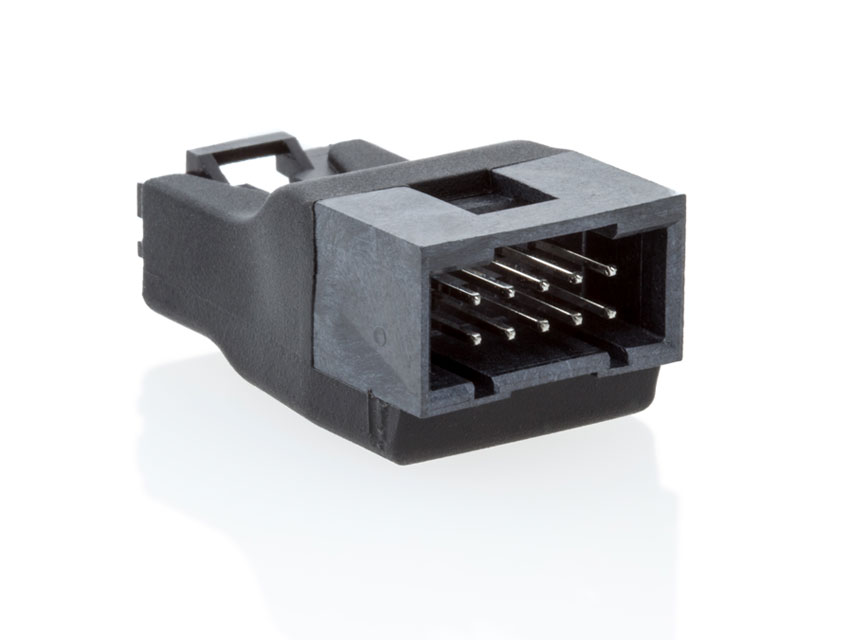
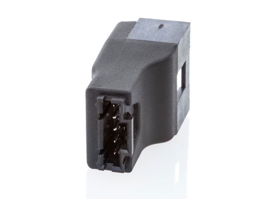
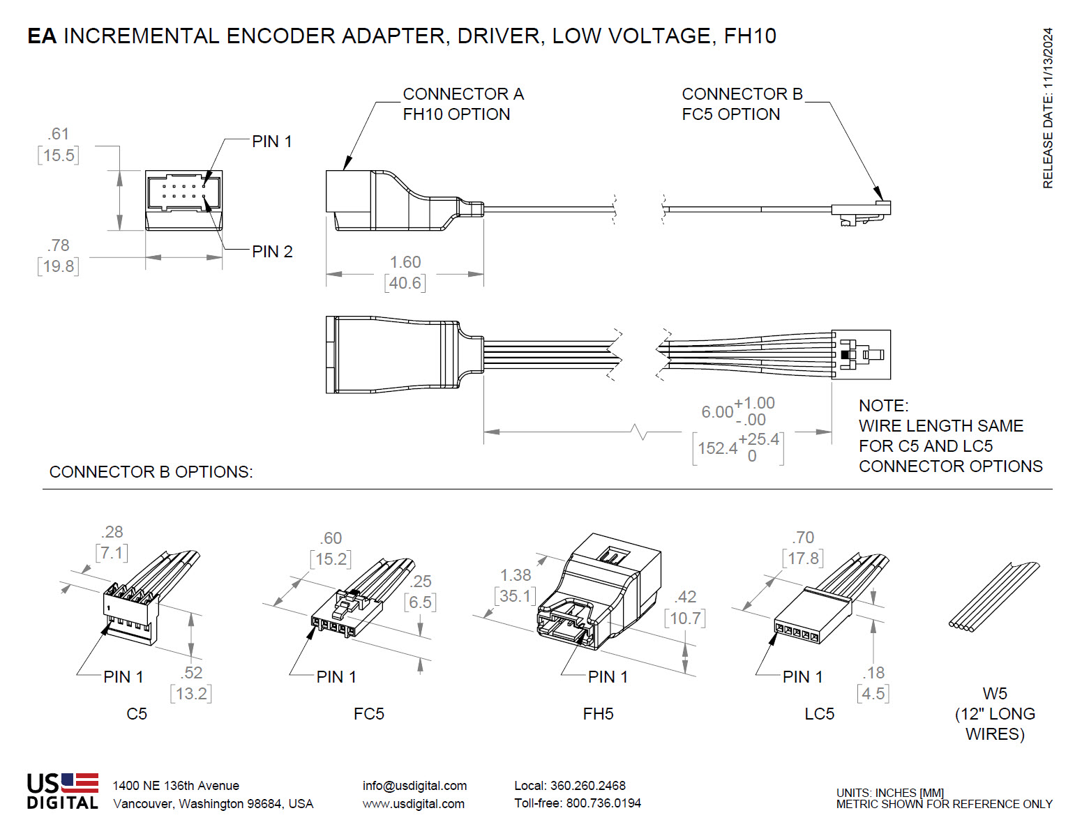
Differential Cable Driver/Receiver The EA-D-L-10- is a differential RS-422 cable driver which converts the single-ended A/B/I output from USD's single-ended incremental encoders (or any three TTL level digital signals) to 3 pairs of differential signals. This allows the encoder to drive long cables (up to 1000 ft.) and reduces false switching in noisy environments. Various connector options are available on the 5-pin input side of this adapter. The output differential signals are available on a male 10-pin latching connector (FH10). The differential signal from the EA-D-L-10- can be connected directly to US Digital's QSB and USB4 interface products.
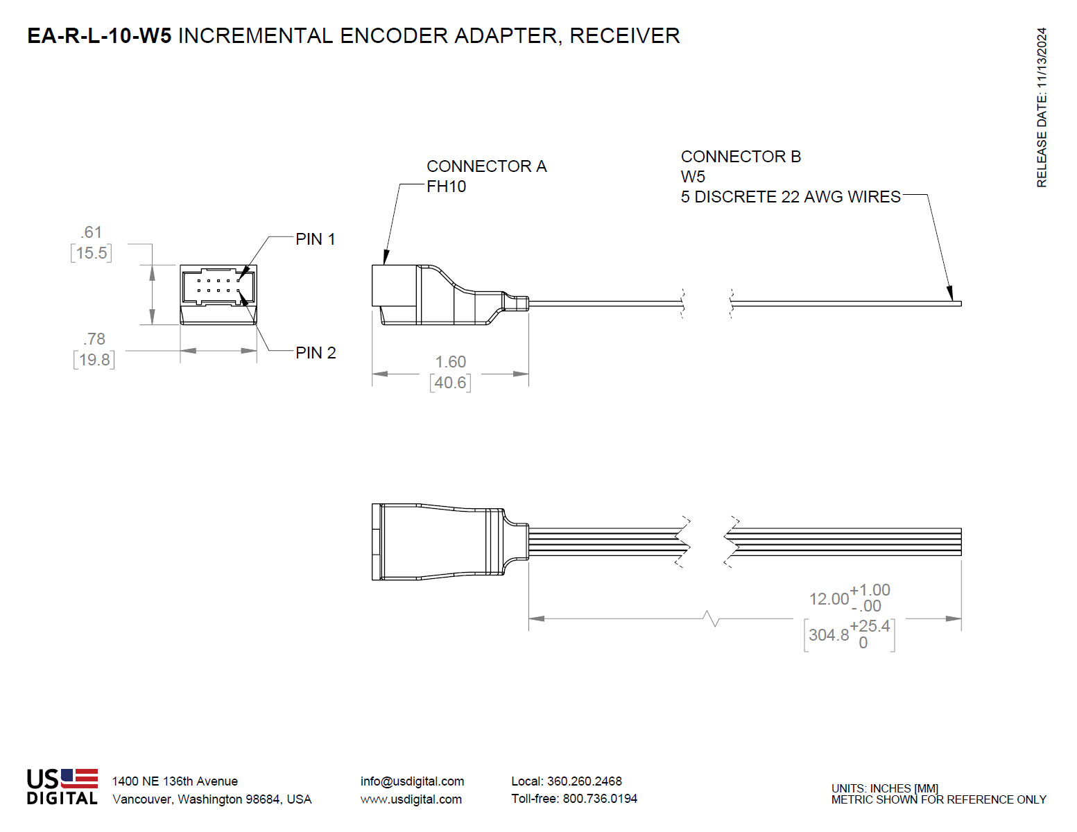
The corresponding receiver, EA-R-L-10-W5 converts the received differential signals back to 3 single-ended TTL level digital signals. The differential input side of the receiver is a 10-pin male latching connector (FH10). The single-ended 5-pin output side has five wires.
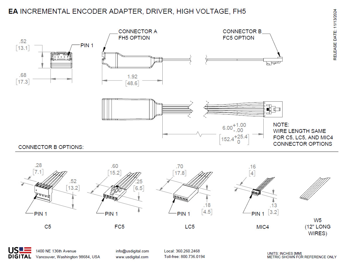
Single-ended Cable Driver The EA-D-H-5- driver converts the single-ended A/B/I output from USD’s incremental encoders (or any 3 TTL level signals) to 3 digital outputs with a large voltage swing proportional to the power supply voltage. The power supply voltage range is 7.5 to 30VDC. The EA-D-H-5- allows 5V encoders to be used in high voltage applications. The output side of the driver is a 5-pin male latching connector (FH5). Various connector options are available on the 5-pin input side.
US Digital can supply nearly any cable to your specifications. See the Cables & Connectors page for more information.
Product Specifications
ENVIRONMENTAL
PARAMETER
VALUE
UNITS
Operating Temperature
-40 to 85
C
Electrostatic Discharge, Human Body Model
± 3
kV
EA-D-L-10- DRIVER ELECTRICAL CHARACTERISTICS
PARAMETER
MIN.
TYP.
MAX.
UNITS
NOTES
Supply Voltage
4.5
5.5
Volts
Supply Current
4.5
9.0
mA
Output High Voltage
2.5
Volts
I(OH) = -20 mA
Output Low Voltage
0.8
Volts
I(OL) = 20 mA
Propagation Time
15
ns
EA-D-H-5- DRIVER ELECTRICAL CHARACTERISTICS
PARAMETER
MIN.
TYP.
MAX.
UNITS
NOTES
Supply Voltage (Vs)
7.5
30
Volts
Encoder Supply Current
200
mA
Propagation Time
236
330
ns
Output Low Voltage
0.5
Volts
Output High Voltage
Vs - 2.0
Volts
Output Current Source/Sink
20
mA
EA-R-L-10-W5 RECEIVER ELECTRICAL CHARACTERISTICS
PARAMETER
MIN.
TYP.
MAX.
UNITS
NOTES
Supply Voltage
4.5
5.5
Volts
Supply Current
16
25
mA
Input High Voltage
2.0
Volts
I(OH) = -20 mA
Input Low Voltage
0.8
Volts
I(OL) = 20 mA
Propagation Time
35
ns
DRIVER (EA-D-) PINOUT
The driver input is a 4-pin or 5-pin connector. See "Connector B Options" for pictures of the available connectors.
FH5 Output Connector:
FH10 Output Connector:
PIN
INPUT 4-PIN CONNECTOR (MIC4)
INPUT 5-PIN CONNECTOR (C5, FC5, FH5, LC5, W5)
EA-D-H-5-
EA-D-L-10-
1
+5VDC power
Ground
Ground
Ground
2
A channel (in)
Index (in)
Index (out)
Ground
3
Ground
A channel (in)
A channel (out)
Index- (out)
4
B channel (in)
+5VDC power
+7.5 to +30VDC power
Index+ (out)
5
B channel (in)
B channel (out)
A- channel (out)
6
A+ channel (out)
7
+5VDC power
8
+5VDC power
9
B- channel (out)
10
B+ channel (out)
Notes:
(1) For the EA-D-L-10, the +5VDC pins on the input and output connectors are electrically connected together, so power can be applied to either the input or output connector. For the EA-D-H-5, the 7.5 to 30VDC power is applied at the OUTPUT connector. +5V out is generated at the INPUT connector.
RECEIVER (EA-R-) PINOUT
The receiver input is a 10-pin latching connector, FH10 (MOLEX# 74162-2010). The output has five 12" discrete wires (W5).
FH10 Input Connector
PIN
INPUT 10-PIN CONNECTOR (FH10)
OUTPUT 5-PIN (W5)
1
Ground
Ground
2
Ground
Index (out)
3
Index- (in)
A channel (out)
4
Index+ (in)
+5VDC power
5
A- channel (in)
B channel (out)
6
A+ channel (in)
7
+5VDC power
8
+5VDC power
9
B- channel (in)
10
B+ channel (in)
Notes:
(1) The +5VDC pins on the input and output connectors are electrically connected, so power can be applied to either the input or output.
CONNECTOR B OPTIONS
OPTION
DESCRIPTION
MANUFACTURER INFO
C5 Five 22 AWG 6" discrete wires with a standard connector
TE# 3-640440-5
FC5 Five 22 AWG 6" discrete wires with a latching connector
MOLEX# 14-56-7052
FH5 5-pin latching header
TE# 2-103634-7
LC5 Five 22 AWG 6" discrete wires with a locking connector
TE# 1-87175-2 (Housing)
MIC4 Four 26 AWG 6" discrete wires with a micro connector
MOLEX# 51021-0400 (Housing)
W5* Five 22 AWG 12" discrete wires
UL 1061-22/7-3
*Note: The W5 pin-out is as follows:
PIN
DESCRIPTION
COLOR
1
Ground
Brown
2
Index
Violet or NC
3
A channel
Blue
4
+5VDC power
Orange
5
B channel
Yellow
Additional Information
Product Notes
US Digital® warrants its products against defects in materials and workmanship for two years. See complete warranty for details.
3D Model Downloads
Please
configure your product first
to download a 3D model. (Note: The formats below will become links if there are 3D models available.)
SolidWorks Format
IGES Format
Parasolid Format
STEP Format
Datasheet
Feedback
US Digital's mission is a commitment to quality and constant improvement. If you find an error to a product on this page, please let us know !
Save Your Configuration
Easily keep track of your custom part numbers
What is this feature?
While configuring your encoder, you can save your custom part number at any stage. This helps you keep track of multiple configurations without needing to start over or write anything down.
How does it work?
Click “Add This Configuration to Your List” after selecting your options.
Your saved part number will appear in a mini list below the configurator.
The list is stored locally in your browser and persists across product pages.
Enter a quantity to view default pricing.
What can you do with saved configurations?
When you're ready, visit the Saved Configurations List page to:
Review all saved part numbers
Fill out a form to send your selections to US Digital Customer Service
Receive follow-up to complete your order or get support
Why use it?
Save time by avoiding repeated configurations
Compare multiple part numbers side-by-side
Simplify communication with our support team
Got it!
 My Saved List