E7P Product Description
THE E7P ENCODER HAS BEEN DISCONTINUED AND THE CURRENT MODEL IS THE E8T .
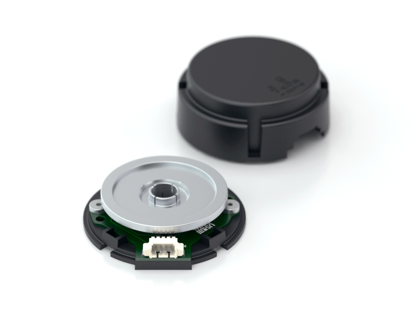
The E7P quick assembly optical incremental kit encoder is designed for high volume, low cost, mid-resolution OEM motion control applications. The E7P was designed as a big brother to the E4P encoder and offers higher resolutions, a wider range of shaft diameters, and mounts to additional bolt circles. The E7P uses a 5V supply and offers two TTL quadrature outputs. A single-chip reflective encoder module incorporates an LED, monolithic detector, and molded lenses. The phased array technology accepts far wider mechanical tolerance and misalignment than traditional aperture type encoders.
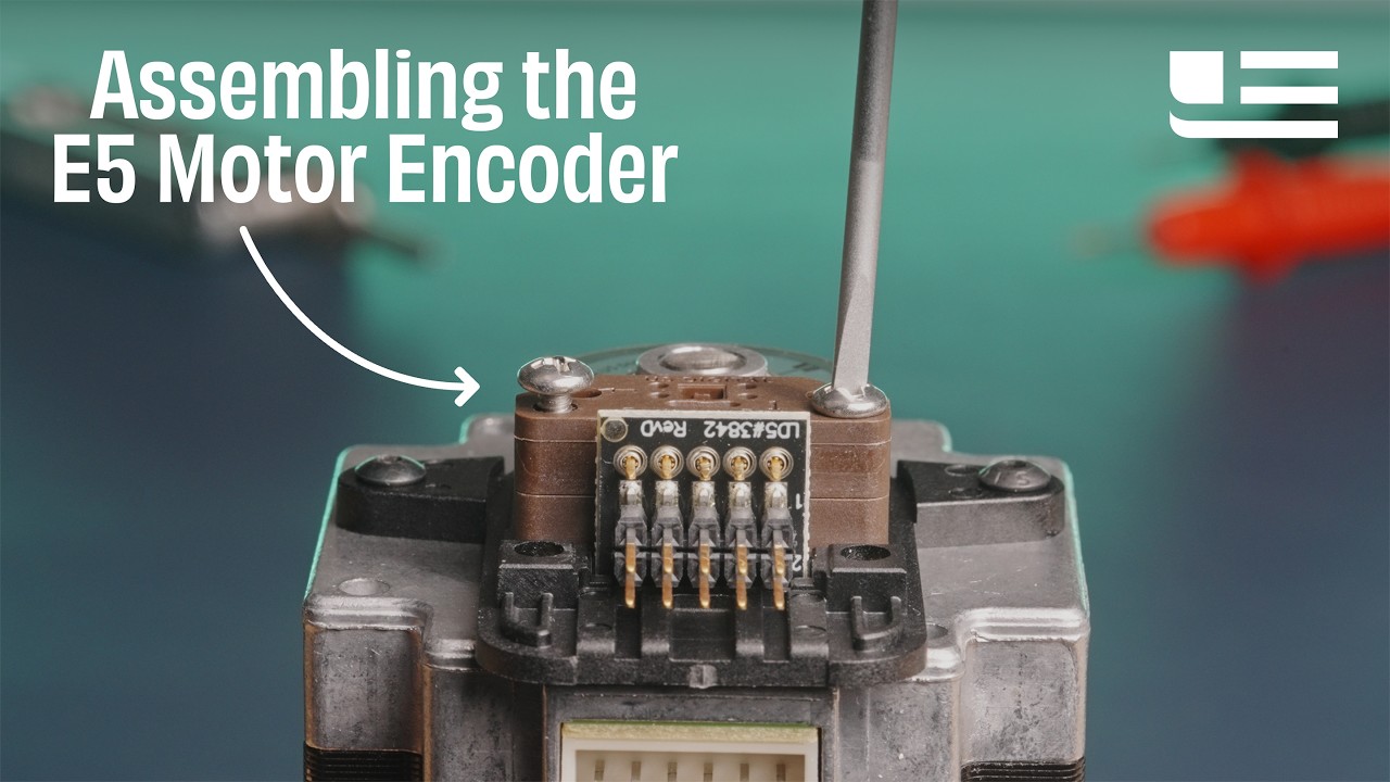
Two screws secure the base using one of the three-bolt circles. The precision-machined aluminum reflective encoder disk pushes on by hand using a spacing tool to securely grip the shaft while eliminating set screws (patent pending). The cover snaps on to complete the assembly in seconds.
When mounting holes are not available, a centering tool and stick-on version are available. The T-option specifies a base with a transfer adhesive pre-applied. The backing is peeled off, and the base is slid down the shaft guided by the centering tool.
The single-ended output version has a 4-pin connector and is designed to drive cables up to six feet long.
The differential output version has a 6-pin connector and is designed for driving longer cable lengths and maximizes noise immunity. The internal 26C31 differential line driver can source and sink 20 mA at TTL levels. The recommended receiver is industry standard 26C32. Maximum noise immunity is achieved when the differential receiver is terminated with a 150 Ω resistor in series with a .0047 μF capacitor placed across each differential pair. The capacitor conserves power. Otherwise, power consumption would increase by approximately 20 mA per pair or 40 mA for 2 pairs.
Product Specifications
ENVIRONMENTAL
PARAMETER
VALUE
UNITS
Vibration (5Hz to 2kHz)
20
G
Max. Relative Humidity
90
%
Storage Temperature
-40 to 100
C
Operating Temperature
-20 to 100
C
Electrostatic Discharge, IEC 61000-4-2S -option)D -option)
MECHANICAL
PARAMETER
VALUE
UNITS
Max. Shaft Axial Play
± .020
in.
Max. Off-axis Mounting Tolerance
± .010
in.
Max. Acceleration
250000
rad/sec²
Maximum RPM (1)
minimum value of
rpm
Codewheel Moment of Inertia
7.03 x 10⁻⁵
oz-in-s2
Required Shaft LengthD -Cover optionC -Cover optionE -Cover optionH -Cover option
Mounting Screw Torque
2-3
in-lbs
Technical Bulletin TB1001 - Shaft and Bore Tolerances
Download
(1) 60000 rpm is the maximum rpm due to mechanical considerations. The maximum rpm due to the module's 30kHz maximum count frequency is (3600000/CPR).
SINGLE-ENDED ELECTRICAL
SPECIFICATIONS
MIN.
TYP.
MAX.
UNITS
NOTES
Supply Voltage
4.5
5.0
5.5
V
Supply Current
21
27
mA
no load
Low-level Output
0.4
V
IOL = 6 mA
High-level Output
2.4
V
IOH = -1 mA
Rise Time
500
ns
CL = 25 pF, RL = 2.7 kΩ
Fall Time
100
ns
DIFFERENTIAL ELECTRICAL
SPECIFICATIONS
MIN.
TYP.
MAX.
UNITS
NOTES
Supply Voltage
4.5
5.0
5.5
V
Supply Current
23
30
mA
Low-level Output
0.2
0.4
V
IOL = 20mA max.
High-level Output
2.4
3.4
V
IOH = -20mA max.
Differential Output Rise/Fall Time
15
ns
PHASE RELATIONSHIP
PARAMETER
TYP.
MAX.
UNITS
Symmetry, S
180 ± 16
180 ± 75
electrical degrees
Quadrature Delay, Q
90 ± 10
90 ± 60
electrical degrees
(1) A leads B for clockwise shaft rotation, and B leads A for counterclockwise rotation viewed from the cover/label side of the encoder.
(2) Typical values represent the encoder performance at typical mounting alignment, whereas the maximum values represent the encoder performance across the range of recommended mounting tolerance.
PIN-OUTS
4-PIN SINGLE-ENDED (1)
6-PIN DIFFERENTIAL (2)
Pin
Description
Pin
Description
1
+5VDC power
1
Ground
2
A channel
2
A channel
3
Ground
3
A- channel
4
B channel
4
+5VDC power
5
B channel
6
B- channel
(1) 4-pin single-ended mating connector is CON-MIC4 CON-MIC6
BASE OPTIONS
The set of screws and hex tool included with each encoder depend on the chosen Base option:
BASE OPTION
BOLT CIRCLE
SCREWS INCLUDED
HEX TOOL INCLUDED
D
0.750" or 1.280"
low profile #4-40 x 1/4"
.050" hex driver
2
1.280"
standard #2-56 x 1/4"
5/64" hex wrench
G
1.812"
standard #4-40 x 1/4"
3/32" hex wrench
T
n/a
none (.005" thick transfer adhesive with peel away backing mount).
none
Although standard socket head cap screws will work when mounting the E7P , to maximize clearance between the codewheel and the top of the screw head, we recommend low profile socket head cap screws when using the holes on the E7P board. Both standard and low profile socket head cap screws will work with the G -option.
0.750" Bolt Circle / Low Profile #4-40 x 1/4":
1.280" Bolt Circle / Low Profile #4-40 x 1/4":
1.280" Bolt Circle / #2-56 x 1/4" (2-option):
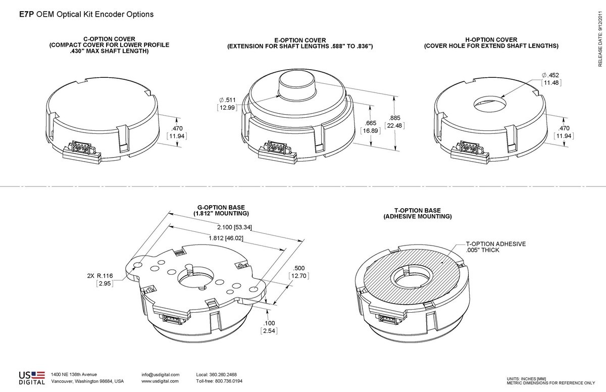
1.812" Bolt Circle / #4-40 x 1/4" (G-option):
T-option: Transfer adhesive base
The T -option base provides a transfer adhesive
COVER OPTIONS
Compact (C-option) provides the lowest profile:
Cover Extension (E-option) provides space in the cover for longer shafts up to 0.836":
Hole in Cover (H-option) provides a 0.452" diameter hole in the cover for shafts:
ACCESSORIES
1. Centering Tool
The centering tool is only included with the -3 packaging option. It has to be ordered separately for other packaging options.
Part #: CTOOL - (Shaft Diameter) Description: This reusable tool provides a simple method for accurately centering the E7P base to the shaft. A centering tool is highly recommended when using the T -option transfer adhesive.
2. Spacer Tool
A spacer tool is included for all packaging options.
Part #: SPACER-E7P Description: This reusable tool is used to properly space the codewheel from the encoder.
PRODUCT CHANGE NOTIFICATION
Title
Date
Description
Download
EOL - E7P - E8P - PCN 5894
02/08/2017
As part of our on-going product lifecycle management process, we have identified products that will be transitioned to an "End-of-Life" status. Products targeted for end-of-life may be available for a last time buy option prior to being made obsolete, however quantities are limited, and special requirements may apply.
Download
Additional Information
Product Notes
Cables and connectors are not included and must be ordered separately.
US Digital® warrants its products against defects in materials and workmanship for two years. See complete warranty for details.
Related
Datasheet
Feedback
US Digital's mission is a commitment to quality and constant improvement. If you find an error to a product on this page, please let us know !
Save Your Configuration
Easily keep track of your custom part numbers
What is this feature?
While configuring your encoder, you can save your custom part number at any stage. This helps you keep track of multiple configurations without needing to start over or write anything down.
How does it work?
Click “Add This Configuration to Your List” after selecting your options.
Your saved part number will appear in a mini list below the configurator.
The list is stored locally in your browser and persists across product pages.
Enter a quantity to view default pricing.
What can you do with saved configurations?
When you're ready, visit the Saved Configurations List page to:
Review all saved part numbers
Fill out a form to send your selections to US Digital Customer Service
Receive follow-up to complete your order or get support
Why use it?
Save time by avoiding repeated configurations
Compare multiple part numbers side-by-side
Simplify communication with our support team
Got it!